Infiniti F50. Manual - part 276


  Index      Infiniti     Infiniti F50 - service repair manual 2006 year


Search            


Content   ..  274  275  276  277   ..


Infiniti F50. Manual - part 276


TROUBLE DIAGNOSIS

BRC-47

C

D

E

G

H

I

J

K

L

M

A

B

BRC

3. 

CHECKING YAW RATE/SIDE G-SENSOR CIRCUIT

Check “DATA MONITOR” for yaw rate /side G-sensor. Check that results are normal.

OK or NG

OK

>> Perform VDC/TCS/ABS control unit self-diagnosis again.

NG

>> Malfunction of yaw rate/side G-sensor. Replace sensor and perform VDC/TCS/ABS control unit

self-diagnosis again.

Inspection 7 Solenoid, VDC Switching Valve, and Circuits

EFS0023W

Inspection Procedure

1. 

CHECKING SELF-DIAGNOSIS RESULTS (1)

Check self-diagnosis results.

Do above items appear on self-diagnosis results display?

YES

>> GO TO 2.

NO

>> Inspection is completed.

2. 

CHECKING SELF-DIAGNOSIS RESULTS (2)

1.

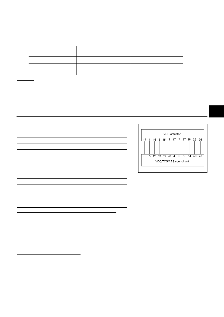
Disconnect VDC/TCS/ABS control unit connector E218 and VDC actuator connector E21, E22, E23.
Then reconnect them securely.

2.

Reconnect connectors securely and perform self-diagnosis again.

Do any self-diagnosis items appear?

YES

>> GO TO 3.

NO

>> Poor connection. Repair or replace applicable connector.

Vehicle condition

Yaw rate sensor

(Data monitor standard)

Side G-sensor

(Data monitor standard)

Stopped

– 4 to +4 deg/s

– 1.1 to +1.1 m/s

2

Turning right

Negative value

Negative value

Turning left

Positive value

Positive value

Self-diagnosis results

CONSULT-II display items

Front LH inlet ABS solenoid system

Front LH outlet ABS solenoid system

Rear RH inlet ABS solenoid system

Rear RH outlet ABS solenoid system

Front RH inlet ABS solenoid system

Front RH outlet ABS solenoid system

Rear LH inlet ABS solenoid system

Rear LH outlet ABS solenoid system

Primary USV solenoid system

Secondary USV solenoid system

Primary MAV solenoid system

Secondary MAV solenoid system

SFIA0611E

BRC-48

TROUBLE DIAGNOSIS

3. 

CHECKING SOLENOID CIRCUIT

1.

Disconnect VDC actuator connector E21,E22 and VDC/TCS/ABS control unit connector E218.

2.

Check continuity between VDC/TCS/ABS control unit harness
connector E218 and VDC actuator harness connector E21,E22.

OK or NG

OK

>> GO TO 4.

NG

>> Open or short in harness between VDC/TCS/ABS control unit and VDC actuator

SFIA0869E

VDC/TCS/ABS control unit

(Harness connector E218)

VDC actuator

(Harness connector E21, E22)

Continuity

26 (W/G)

3 (W/G)

Yes

5 (G/Y)

1 (G/Y)

Yes

6 (L/W)

7 (L/W)

Yes

53 (P)

5 (P)

Yes

55 (R/Y)

15 (R/Y)

Yes

3 (Y/G)

14 (Y/G)

Yes

4 (BR)

17 (BR)

Yes

25 (LG)

16 (LG)

Yes

52 (PU)

27 (PU)

Yes

54 (W)

28 (W)

Yes

50 (R/G)

25 (R/G)

Yes

49 (W/R)

26 (W/R)

Yes

TROUBLE DIAGNOSIS

BRC-49

C

D

E

G

H

I

J

K

L

M

A

B

BRC

4. 

CHECKING ACTUATOR SOLENOID

1.

Disconnect VDC actuator connector.

2.

Check resistance of VDC actuator solenoid.

OK or NG

OK

>> Perform VDC/TCS/ABS control unit self-diagnosis again.

NO

>> Replace VDC actuator assembly.

Inspection 8 Actuator Motor, Motor Relay, and Circuit

EFS001ZJ

Inspection Procedure

1. 

CHECKING SELF-DIAGNOSIS RESULTS (1)

Check self-diagnosis results.

Do “PUMP MOTOR” and “MOTOR RELAY SYSTEM” appear in self-diagnosis results display?

YES

>> GO TO 2.

NO

>> Inspection is completed.

SFIA0965E

VDC actuator

(Actuator side connector)

VDC actuator

(Actuator side connector)

Resistance value

19

6.0 - 11 

19

6.0 - 11 

19

6.0 - 11 

19

6.0 - 11 

17 19

3.0 

5.0 

15 19

3.0 

5.0 

16 19

3.0 

5.0 

14

19

3.0 - 5.0 

27 19

3.0 

5.0 

28 19

3.0 

5.0 

25

19

6.0 - 11 

26

19

6.0 - 11 

Self-diagnosis results

CONSULT-II display items

Pump motor, motor relay system

BRC-50

TROUBLE DIAGNOSIS

2. 

CHECKING SELF-DIAGNOSIS RESULTS (2)

1.

Disconnect VDC/TCS/ABS control unit connector E218 and VDC relay box connector E55, E56, E57.
Then reconnect them securely.

2.

Reconnect connectors securely and perform self-diagnosis again.

Do any self-diagnosis items appear?

YES

>> GO TO 3.

NO

>> Poor connection. Repair or replace applicable connector.

3. 

CHECKING ABS MOTOR AND MOTOR RELAY POWER SYSTEM

1.

Disconnect VDC relay box connector E57.

2.

Check voltage between VDC relay box harness connector E57
and body ground.

OK or NG

OK

>> GO TO 4.

NG

>>

Check fuse 50A.

Check that there is continuity between battery and relay unit terminal No. 10 (W/L).

4. 

CHECKING ABS MOTOR AND MOTOR RELAY CIRCUIT

1.

Disconnect VDC/TCS/ABS control unit E218 and VDC relay box connector E56.

2.

Check continuity between VDC/TCS/ABS control unit harness
connector E218 and VDC relay box harness connector E56.

OK or NG

OK

>> GO TO 5.

NG

>> Open or short in harness between VDC/TCS/ABS control unit and relay unit/actuator

SFIA0875E

VDC relay box

(Harness connector E57)

Body ground

Voltage

10 (W/L)

Battery voltage (Approx. 12V)

SFIA0876E

VDC/TCS/ABS control unit

(Harness connector E218)

VDC relay box

(Harness connector E56)

Continuity

20 (R/B)

4 (R/B)

Yes

7 (G/W)

8 (G/W)

Yes


Content   ..  274  275  276  277   ..