Infiniti F50. Manual - part 242
IVIS (INFINITI VEHICLE IMMOBILIZER SYSTEM-NATS)
BL-215
C
D
E
F
G
H
J
K
L
M
A
B
BL
3.
PERFORM INITIALIZATION WITH CONSULT-II
Perform initialization with CONSULT-II.
For initialization, refer to “CONSULT-II Operation Manual NATS-
IVIS/NVIS”.
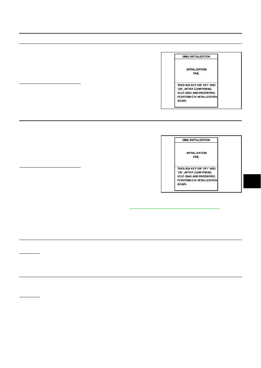
NOTE:
If the initialization is not completed or malfunctions, CONSULT-II
shows the message on the screen.
Can the system be initialized?
Yes
>> System is OK.
No
>> GO TO 4
4.
PERFORM INITIALIZATION WITH CONSULT-II AGAIN
1.
Replace NATS IMMU.
2.
Perform initialization with CONSULT-II.
For initialization, refer to “CONSULT-II Operation Manual NATS-
IVIS/NVIS”.
NOTE:
If the initialization is not completed or malfunctions, CONSULT-II
shows the message on the screen.
Can the system be initialized?
Yes
>> System is OK. NATS IMMU is malfunctioning. Ref. part
No. A )
No
>> ECM is malfunctioning.
●
Replace ECM. Ref. part No. B
●
Perform initialization or re-communicating function.
–
For initialization, refer to “CONSULT-II Operation Manual NATS-IVIS/NVIS”.
–
For re-communicating function, refer to
BL-200, "ECM Re-communicating Function"
Diagnostic Procedure 6
EIS0043L
Self-diagnostic results:
“CHAIN OF IMMU-KEY” displayed on CONSULT-II screen
1.
CHECK OF ELECTRONIC KEY (TRANSPONDER)
Using the other registered electronic key, check that the ignition switch can be turned ON.
OK or NG
OK
>> Electronic key (transponder) malfunction. Ref. part D.
NG
>> GO TO 2.
2.
CHECK NATS ANTENNA AMP. INSTALLATION
1.
Turn ignition switch OFF.
2.
Check the installation condition of the NATS antenna amp.
OK or NG
OK
>> GO TO 3.
NG
>> Install the NATS antenna amp. correctly. Reference part E.
SEL297W
SEL297W