Infiniti F50. Manual - part 199
POWER DOOR LOCK SYSTEM
BL-43
C
D
E
F
G
H
J
K
L
M
A
B
BL
Symptom Chart
EIS003QU
●
Always check the “Work Flow” before troubleshooting. Refer to
.
●
Before carrying out the inspection on the following table, carry out the preliminary check.
Refer to
Check Communication Line
EIS003O8
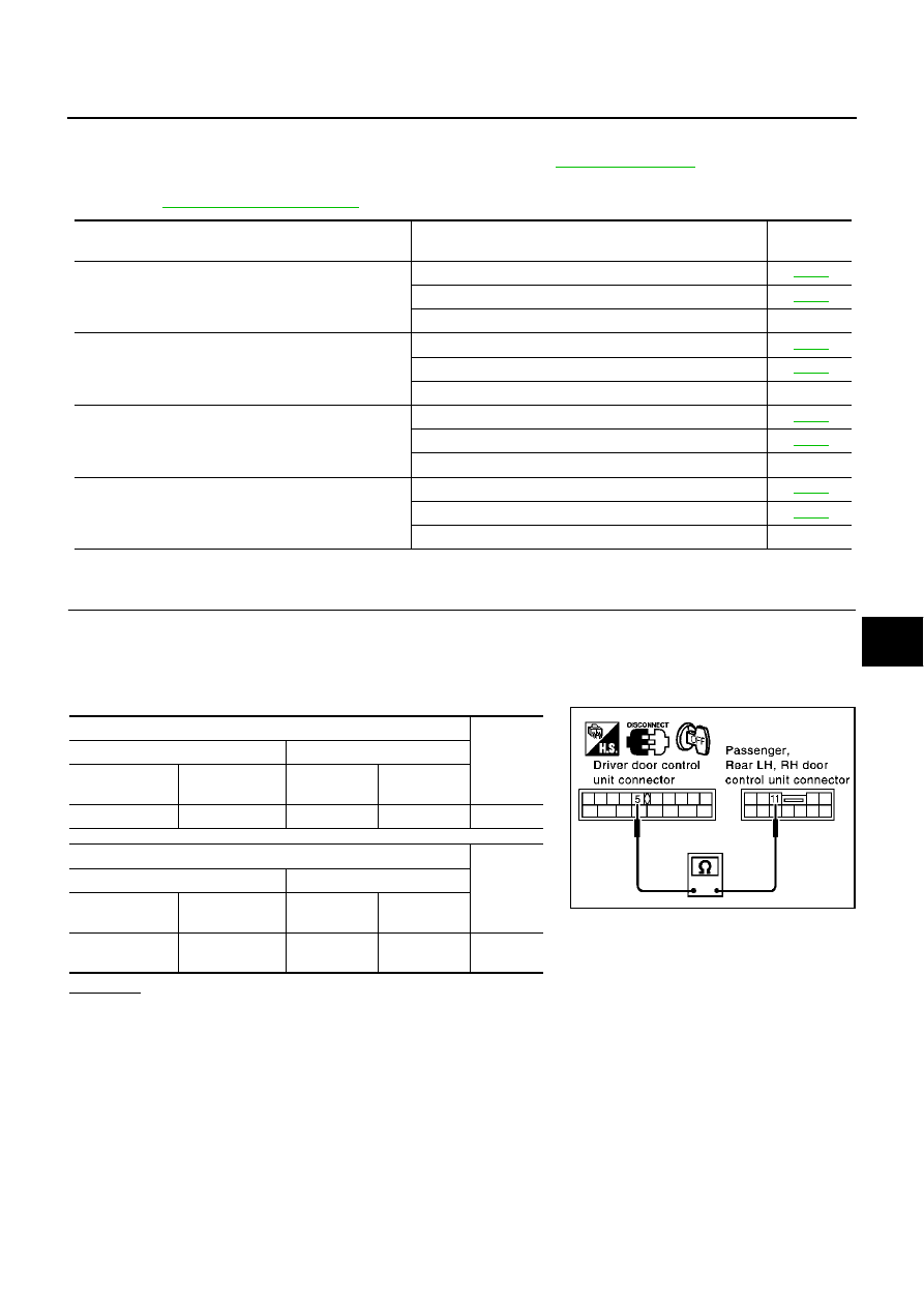
1.
CHECK COMMUNICATION CIRCUIT
1.
Turn ignition switch OFF.
2.
Disconnect connectors for driver door control unit (LCU01) and malfunctioning door control unit.
3.
Check continuity between driver door control unit (LCU01) connector terminal 5 (G/OR) and malfunction-
ing door control unit connector terminal 11 (G/OR).
OK or NG
OK
>> GO TO 2.
NG
>> Repair or replace harness.
Symptom
Diagnosis procedure
Reference
page
Power door lock does not operate with door lock and
unlock switch on power window main switch.
1. Check door lock and unlock switch.
2. Check communication line.
3. Replace driver door control unit (LCU01).
–
Specific door lock actuator does not operate.
1. Check door lock actuator (Passenger, Rear LH, RH).
2. Check communication line.
3. Replace door control unit.
–
Power door lock does not operate with front key cylinder
switch operation.
1. Check front door key cylinder switch.
2. Check communication line.
3. Replace driver door control unit (LCU01).
–
Key reminder door system does not operate properly.
1. Check front door switch.
2. Check key switch.
3. Replace BCM.
–
Terminal
Continuity
Driver door control unit (LCU01)
Passenger door control unit
Connector
Terminal
(Wire color)
Connector
Terminal
(Wire color)
D8
5 (G/OR)
D38
11 (G/OR)
Yes
Terminal
Continuity
Driver door control unit (LCU01)
Rear door control unit
Connector
Terminal
(Wire color)
Connector
Terminal
(Wire color)
D8
5 (G/OR)
D58 (LH)
D78 (RH)
11 (G/OR)
Yes
PIIA3250E