Infiniti F50. Manual - part 196
 

  Index      Infiniti     Infiniti F50 - service repair manual 2006 year


Search            


Content   ..  194  195  196  197   ..


Infiniti F50. Manual - part 196


POWER DOOR LOCK SYSTEM

BL-31

C

D

E

F

G

H

J

K

L

M

A

B

BL

(

): Wire color for rear RH/LH door control unit.

Work Flow

EIS00134

1.

Check the symptom and customer's requests.

2.

Understand the outline of system. Refer to 

BL-20, "System Description"

 .

3.

Perform the preliminary check. Refer to 

BL-31, "Preliminary Check"

 .

4.

Perform the communication inspection. If CONSULT-II is used, refer to 

BL-35, "IVMS COMMUNICATION

INSPECTION"

  section. If CONSULT-II is not used, refer to 

BL-38, "COMMUNICATION DIAGNOSIS"

 . Is

the communication diagnosis result OK?
OK: GO TO step 7.
NG: GO TO step 5

5.

Repair or replace depending on the diagnosis result.

6.

Perform the communication diagnosis again. If CONSULT-II is used, refer to 

BL-35, "IVMS COMMUNICA-

TION INSPECTION"

 . If CONSULT-II is not used, refer to 

BL-38, "COMMUNICATION DIAGNOSIS"

 . Is

communication diagnosis result OK?
OK: GO TO step 7.
NG: GO TO step 5.

7.

Perform the self-diagnosis. If CONSULT-II is used, refer to 

BL-35, "IVMS COMMUNICATION INSPEC-

TION"

 . If CONSULT-II is not used, refer to 

BL-38, "COMMUNICATION DIAGNOSIS"

 . Is self-diagnosis

result OK?
OK: GO TO step 11.
NG: GO TO step 8.

8.

Repair or replace depending on the diagnosis result.

9.

Perform the self-diagnosis again. If CONSULT-II is used, refer to 

BL-37, "SELF-DIAGNOSIS RESULTS"

 ,

If CONSULT-II is not used, refer to 

BL-42, "POWER DOOR LOCK SYSTEM SELF-DIAGNOSIS"

 . Is self-

diagnosis result OK?
OK: GO TO step 11.
NG: GO TO step 8.

10. Referring to trouble diagnosis chart, repair or replace the cause of the incident.

Refer to 

BL-43, "Symptom Chart"

11. Does power door lock system operate normally?

YES: GO TO step 12.
NO: GO TO step 10.

12. Inspection END.

Preliminary Check

EIS00135

POWER SUPPLY AND GROUND CIRCUIT INSPECTION

1. 

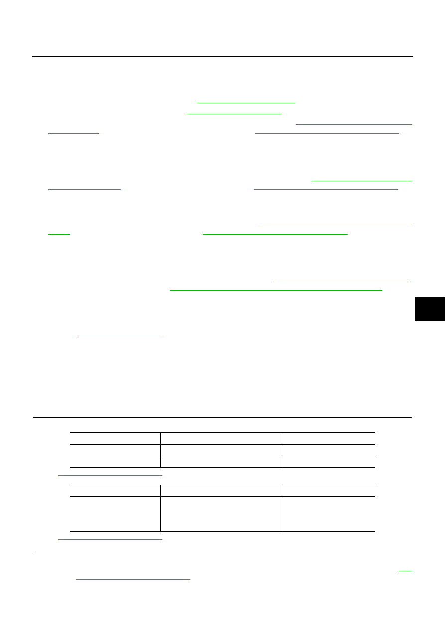
FUSE INSPECTION

Check if any of the following fuses are blown.

Refer to 

BL-22, "Wiring Diagram – D/LOCK –"

 .

Refer to 

BL-22, "Wiring Diagram – D/LOCK –"

 .

OK or NG

OK

>> GO TO 2.

NG

>> If fuse is blown, be sure to eliminate cause of malfunction before installing new fuse, refer to 

PG-

2, "POWER SUPPLY ROUTING"

 .

Unit

Power source

Fuse No.

BCM

Battery power supply

3 (10A)

IGN power supply

1 (10A)

Unit

Power source

Fusible link location

Driver door control unit
Passenger door control unit
Rear LH door  control unit
Rear RH door control unit

Battery power supply

H (40A)

BL-32

POWER DOOR LOCK SYSTEM

2. 

POWER SUPPLY CIRCUIT INSPECTION

Remove the connectors for BCM and driver door LCU or passenger,
rear LH, RH door control units, measure the voltage between the fol-
lowing terminals of connector and ground.

OK or NG

OK

>> GO TO 3.

NG

>> Check harness for open or short.

Unit

Terminals

(wire color)

Ignition

switch

condition

Voltage (V)

Approx.

Connector

(+)

(–)

BCM (M4)

105 (Y/L)

Ground

OFF

Battery voltage

68 (W/B)

ON

Driver door control unit 
(D8)

14 (Y/G)

OFF

Passenger door control 
unit (D39)

6 (W/R)

OFF

Rear LH door control unit 
(D59)

6 (Y/B)

Rear RH door control 
unit (D79)

6 (Y/B)

PIIA4454E

POWER DOOR LOCK SYSTEM

BL-33

C

D

E

F

G

H

J

K

L

M

A

B

BL

3. 

GROUND CIRCUIT INSPECTION

Check the continuity between the following terminals connector for
BCM, driver door LCU,   passenger or rear RH, LH door control units
and ground.

OK or NG

OK

>> Power supply and ground circuit is OK.

NG

>> Repair or replace harness.

CONSULT-II Function

EIS00136

CONSULT-II executes the following functions by combining data reception and command transmission via the
communication line from BCM. IVMS communication inspection, work support (only function setting of seats
and steering wheel), self-diagnosis, data monitor, and active test display.

DIAGNOSTIC ITEMS DESCRIPTION

Unit

Terminal

(wire color)

Continuity

Connector

(+)

(–)

BCM (M4)

56 (B)

Ground

Continuity should exist

113 (B)

Driver door control unit 
(D8)

15 (B)

Passenger door control 
unit (D39)

7 (B)

Rear LH door control unit 
(D59)

Rear RH door control unit 
(D79)

PIIA4473E

IVMS diagnosis 

position

 Diagnosis mode

Description

IVMS-
COMM CHECK

IVMS-
COMM DIAGNOSIS

Diagnosis of continuity in the communication line(s), and of the function of the 
IVMS-communication interface between the body control module and the 
local control units, accomplished by transmitting a signal from the body con-
trol module to the local control units.

WAKE-UP DIAGNOSIS

Diagnosis of the“ wake-up” function of local control units by having a techni-
cian input the switch data into the local control unit that is in the temporary 
“sleep” condition.

BL-34

POWER DOOR LOCK SYSTEM

CONSULT-II BASIC OPERATION PROCEDURE

1.

With the ignition switch OFF, connect “CONSULT-II” and “CON-
SULT-II CONVERTER” to the data link connector, and turn the
ignition switch ON.

2.

Touch "START (NISSAN BASED VHCL)".

3.

Touch "IVMS".
If “IVMS” is not indicated, go to

GI-38, "CONSULT-II Data Link

Connector (DLC) Circuit"

 .

Each system 
inspection

Work support

Changes the setting for each function.

Self-diagnosis results

Carries out self-diagnosis.

Data monitor

Displays data relative to the body control module (BCM) input signals and var-
ious control related data for each system.

Active test

Turns on/off actuators, relay and according to the commands transmitted by 
the CONSULT-II unit.

BCM PART NUMBER

Displays BCM part No.

IVMS diagnosis 

position

 Diagnosis mode

Description

SHIA0179E

MBIB0233E

PIIA0183E


Content   ..  194  195  196  197   ..