Infiniti F50. Manual - part 166


  Index      Infiniti     Infiniti F50 - service repair manual 2006 year


Search            


Content   ..  164  165  166  167   ..


Infiniti F50. Manual - part 166


AUDIO

AV-29

C

D

E

F

G

H

I

J

L

M

A

B

AV

Power Supply Circuit Inspection

EKS000Y0

1. 

CHECK FUSE

Make sure the following fuses of the BOSE speaker amplifier, audio unit, CD auto changer and rear con-
trol cancel switch are not blown. Refer to 

PG-66, "FUSE BLOCK - JUNCTION BOX (J/B) NO.1"

 .

PG-69,

"FUSE, FUSIBLE LINK AND RELAY BOX"

 .

OK or NG

OK

>> GO TO 2.

NG

>> If fuse is blown be sure to eliminate cause of malfunction before installing new fuse. Refer to 
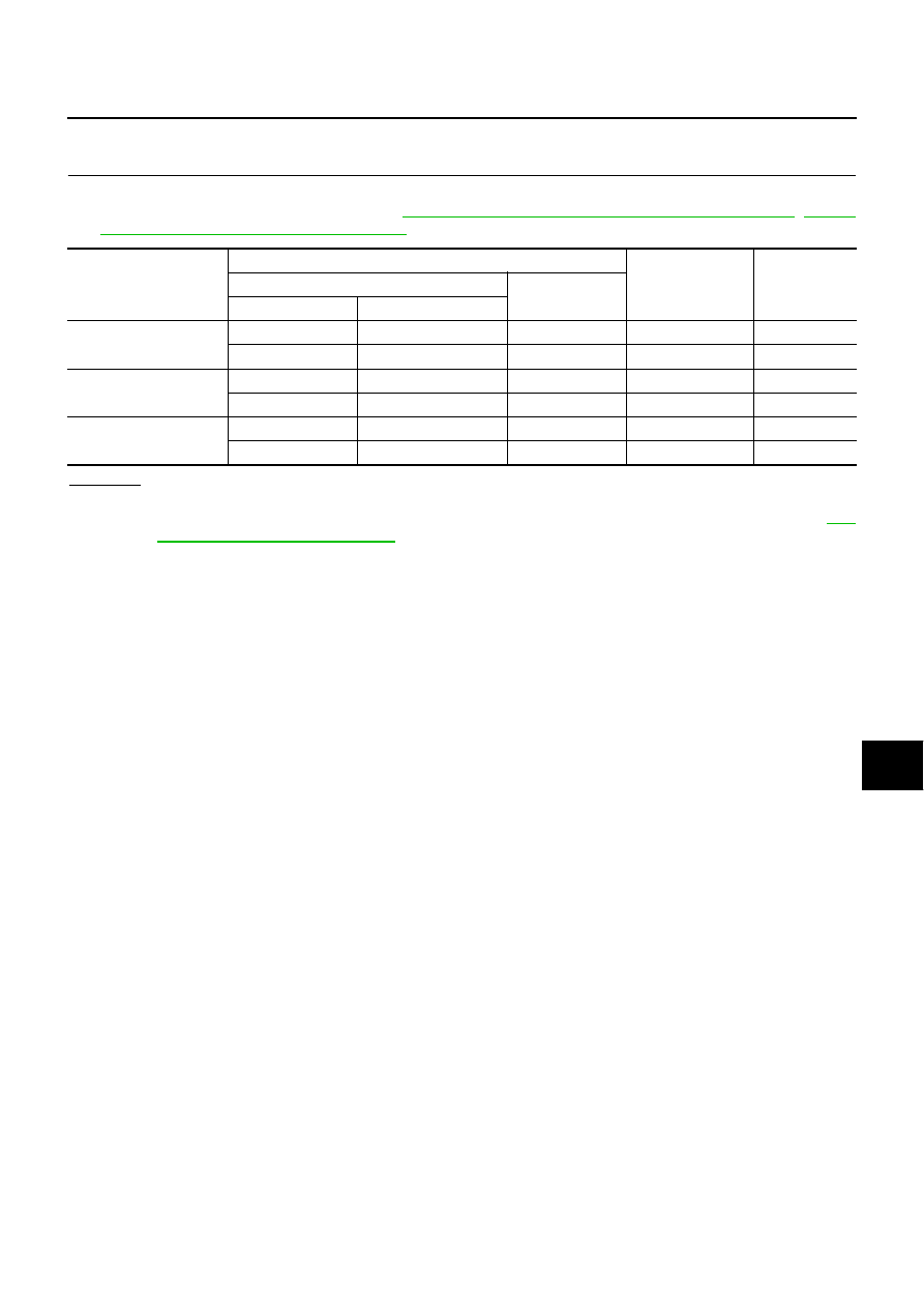
PG-

2, "POWER SUPPLY ROUTING"

 .

Unit

Terminals

Signal name

Fuse No.

(+)

(-)

Connector

Terminal (Wire color)

BOSE speaker amplifier

B233

11 (L)

Ground

Battery power

J

B234

34 (OR/L)

Ground

ACC power

21

Audio unit

M86

73 (SB)

Ground

Battery power

52

M86

72 (L/OR)

Ground

ACC power

21

CD auto changer

M109

12 (SB)

Ground

Battery power

52

M109

16 (L/OR)

Ground

ACC power

21

AV-30

AUDIO

2. 

CHECK POWER SUPPLY CIRCUIT

Disconnect the each unit connector. Check voltage between the fol-
lowing harness connector terminal (+) and ground (-).

OK or NG

OK

>> Inspection end.

NG

>> Check harness for open or short between each unit and

fuse or fusible link.

Audio System Does Not Turn On

EKS000Y1

1. 

SELF-DIAGNOSIS

1.

Perform self-diagnosis. Refer to 

AV-78, "Self-Diagnosis Mode"

  for models with navigation system and 

DI-

109, "Self-Diagnosis Mode"

 for models without navigation system.

OK or NG

OK

>> Replace audio unit.

NG

>> Check the malfunctioned area according to the self-diagnosis result.

Steering Switch Does Not Operate

EKS001JP

1. 

SELF-DIAGNOSIS MODE OF MULTI-FUNCTION SWITCH

1.

Carry out the self-diagnosis mode in the self-diagnosis function. 

2.

Push steering switch.

OK or NG

OK

>> GO TO 2.

NO

>> GO TO 3.

Unit

Terminal No.

Power 

Source

Ignition 

switch

Reference 

voltage (V)

(+)

(-)

Connector

Terminal 

(Wire 

color)

BOSE 
speaker 
amplifier

B233

11 (L)

Ground

Battery 

power

OFF

Battery 
voltage

B234

34 (OR/L)

Ground

ACC

power

ACC

Battery 
voltage

Audio unit

M86

73 (SB)

Ground

Battery 

power

OFF

Battery 
voltage

M86

72 (L/OR)

Ground

ACC 

power

ACC

Battery 
voltage

CD Auto 
changer

M109

12 (SB)

Ground

Battery 

power

OFF

Battery 
voltage

M109

16 (L/OR)

Ground

ACC 

power

ACC

Battery 
voltage

SKIA3614E

Beep sound should operate.

AUDIO

AV-31

C

D

E

F

G

H

I

J

L

M

A

B

AV

2. 

SELF-DIAGNOSIS MODE OF AV COMMUNICATION LINE

1.

Carry out the self-diagnosis mode in the self-diagnosis function. Refer to 

AV-78, "Self-Diagnosis Mode"

(with navigation system) or refer to 

DI-109, "Self-Diagnosis Mode"

 .

Dose self–diagnosis start?

YES

>> With self-diagnosis results, check the malfunction part.

NO

>>

Check multi-function switch of power supply and ground circuit check. Refer to 

DI-121, "Inspec-

tion of Multifunction Switch for Power Supply and Ground Circuit"

 .

Check harness between multi-function switch and AV and NAVI control unit or AV control unit.

3. 

CHECK STEERING SWITCH CIRCUIT

1.

Turn ignition switch OFF.

2.

Disconnect steering switch connector and multi-function switch connector.

3.

Check the following.

Continuity between steering switch harness connector M444 terminal 2  (L) and multi-function switch har-
ness connector M83 terminal 7 (GY/L).

Continuity between steering switch harness connector M444 terminal 2 (L) and ground.

OK or NG

OK

>> GO TO 4.

NG

>> Check the following.

Harness between for open or short steering switch and spiral cable.

Connector housing terminal for disconnection and looseness.

4. 

CHECK HORN OPERATION

1.

Check horn operation.

OK or NG

OK

>> GO TO 5.

NG

>> Check horn system.

5. 

CHECK POWER SUPPLY CIRCUIT

1.

Connect steering switch connector.

2.

Turn the ignition switch ON.

3.

Check harness between steering switch harness connector
M444 terminal 1(R) and ground.

OK or NG

OK

>> GO TO 6

NG

>> Check harness for open or short between steering

switch and horn relay [located in fuse, fusible link and
relay block (J/B)]

Terminals

Continuity

(+)

(–)

Connector

Terminal

(Wire color)

Connector

Terminal

(Wire color)

M444

2 (L)

M83

7 (GY/L)

Yes

M444

2 (L)

Ground

No

SKIA0537E

Horn should operate.

Battery voltage should exist.

SKIA0538E

AV-32

AUDIO

6. 

 CHECK STEERING SWITCH GROUND CIRCUIT

1.

Disconnect steering switch connector.

2.

Check harness between steering switch harness connector
M444 terminal 3 (B) and ground.

OK or NG

OK

>> Replace steering switch.

NG

>> Repair or replace harness.

Rear Control Switch Audio Operation Does Not Work

EKS001JQ

1. 

CONFIRM OF OPERATION

1.

Is it activated by normal audio operation?

YES or NO

YES

>> GO TO 2.

NO

>> Refer to 

AV-30, "Audio System Does Not Turn On"

2. 

SELF-DIAGNOSIS

1.

Carry out the self-diagnosis mode in the self-diagnosis function. For models with navigation, refer to 

AV-

78, "Self-Diagnosis Mode"

 , and for models without navigation, refer to 

DI-109, "Self-Diagnosis Mode"

 .

Is the self-diagnosis result OK?

OK

>> GO TO 3.

NG

>> With self-diagnosis results, check the faulty part.

3. 

REAR CONTROL SWITCH OPEN OR SHORT CIRCUIT

1.

Turn ignition switch OFF.

2.

Disconnect rear control switch connector and multi-function switch connector.

3.

Check the following.

Continuity harness between rear control switch harness connector B502 terminal  10(Y) and multi-func-
tion switch harness connector M83 terminal 8 (Y). 

Continuity between rear control switch harness connector B502 terminal 10 (Y) and ground.

OK or NG

OK

>> Replace rear control switch.

NG

>> Repair or replace harness.

Continuity should exist.

SKIA0539E

Terminals

Continuity

(+)

(–)

Connector

Terminal

(Wire color)

Connector

Terminal

(Wire color)

B502

10 (Y)

M83

8 (Y)

Yes

B502

10 (Y)

Ground

No

SKIA0540E


Content   ..  164  165  166  167   ..