Infiniti F50. Manual - part 140


  Index      Infiniti     Infiniti F50 - service repair manual 2006 year


Search            


Content   ..  138  139  140  141   ..


Infiniti F50. Manual - part 140


TROUBLE DIAGNOSIS

ATC-85

C

D

E

F

G

H

I

K

L

M

A

B

ATC

4. 

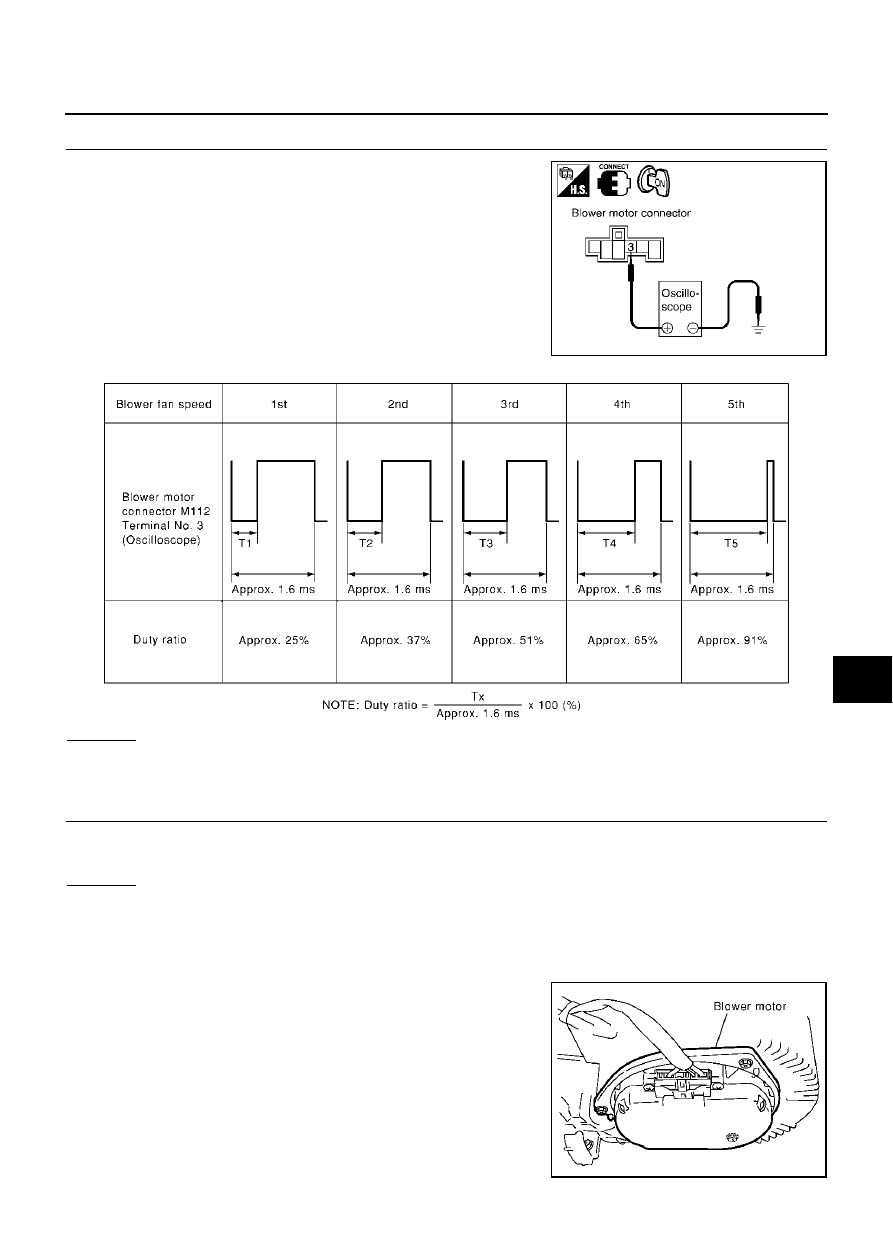
CHECK FOR AUTO AMP. OUTPUT

1.

Reconnect blower motor connector and auto amp. connector.

2.

Turn ignition switch ON.

3.

Vary the fan speed between Lo and Hi and confirm the blower
motor connector terminal 3 (L/OR) duty ratios using an oscillo-
scope. Normal terminal 3 (L/OR) drive signal duty ratios are
shown in the table below.

OK or NG

OK

>> GO TO 5.

NG

>> Replace auto amp.

5. 

CHECK BLOWER MOTOR DRIVE SIGNAL

If the fan air flow does not change, normal terminal 3 (L/OR) drive signal duty ratios are shown in the table
above.

OK or NG

OK

>> Replace blower motor.

NG

>> INSPECTION END

COMPONENT INSPECTION
Blower Motor

Confirm smooth rotation of the blower motor.

Ensure that there are no foreign particles inside the intake unit.

RJIA1603E

RJIA0338E

RJIA0271E

TROUBLE DIAGNOSIS

ATC-87

C

D

E

F

G

H

I

K

L

M

A

B

ATC

SYSTEM DESCRIPTION

Auto amplifier controls compressor operation by ambient temperature and signal from ECM.

Low Temperature Protection Control

Unified meter and A/C amp. (auto amp.). Will Turn compressor ON or OFF as determined by a signal detected
by ambient sensor and intake sensor.
When ambient temperatures are greater than -2

°

C (28

°

F), the com-

pressor turns ON. The compressor turns OFF when ambient temper-
atures are less than -5

°

C (23

°

F).

When intake air temperatures are greater than 1

°

C (34

°

F), the com-

pressor turns ON. The compressor turns OFF when intake air tem-
peratures are less than -5

°

C (23

°

F).

DIAGNOSTIC PROCEDURE FOR MAGNET CLUTCH

SYMPTOM: Magnet clutch does not engage when AUTO switch is ON.

RHA094GB

SJIA0267E

RJIA0294E

ATC-88

TROUBLE DIAGNOSIS

1. 

CHECK POWER SUPPLY FOR COMPRESSOR

1.

Disconnect compressor connector.

2.

Start engine and AUTO switch ON.

3.

Check voltage between compressor (magnet clutch) harness
connector F2 terminal 1 (Y/R) and ground.

OK or NG

OK

>> Check magnet clutch coil.

1. If NG, replace magnet clutch. Refer to 

ATC-145,

"Compressor Clutch"

 .

2. Go to 

ATC-54, "FUNCTION CONFIRMATION PRO-

CEDURE"

  and perform self-diagnosis STEP-4. Confirm that magnet clutch operation is nor-

mal.

NG

>> GO TO 2.

2. 

CHECK CIRCUIT CONTINUITY BETWEEN A/C RELAY AND COMPRESSOR

1.

Turn ignition switch OFF.

2.

Disconnect A/C relay.

3.

Check continuity between compressor (magnet clutch) harness
connector F2 terminal 1 (Y/R) and A/C relay harness connector
E3-2 terminal 3 (Y/R).

OK or NG

OK

>> Check harness for short. And GO TO 3.

NG

>> Repair harness or connector.

3. 

CHECK POWER SUPPLY FOR A/C RELAY

1.

Turn ignition switch ON.

2.

Check voltage between A/C relay harness connector E3-2 termi-
nals 2, 5 and ground.

OK or NG

OK

>> GO TO 4.

NG

>> Check power supply circuit and 10A fuse [No. 51 

located in the fuse, fusible link and relay block (J/B)]. 
Refer to 

PG-3, "BATTERY POWER SUPPLY— IGNI-

TION SW. IN ANY POSITION"

 .

If OK, check for open circuit in wiring harness. Repair or replace as necessary.

If NG, replace fuse and check wiring harness for short circuit. Repair or replace as necessary.

4. 

CHECK A/C RELAY AFTER DISCONNECTING IT

Refer to 

ATC-91, "A/C Relay"

 .

OK or NG

OK

>> GO TO 5.

NG

>> 1. Replace A/C relay.

2. Go to 

ATC-54, "FUNCTION CONFIRMATION PROCEDURE"

  and perform self-diagnosis

STEP-4. Confirm that magnet clutch operation is normal.

1 – Ground

: Battery voltage

RJIA0295E

1 – 3

: Continuity should exist.

RJIA0296E

2, 5 – Ground

: Battery voltage

RJIA0297E


Content   ..  138  139  140  141   ..