Infiniti F50. Manual - part 79


  Index      Infiniti     Infiniti F50 - service repair manual 2006 year


Search            


Content   ..  77  78  79  80   ..


Infiniti F50. Manual - part 79


DTC P1767 HIGH AND LOW REVERSE CLUTCH SOLENOID VALVE

AT-201

D

E

F

G

H

I

J

K

L

M

A

B

AT

Component Inspection

ECS00A35

HIGH AND LOW REVERSE CLUTCH SOLENOID VALVE
Resistance check

1.

Turn ignition switch “OFF”.

2.

Remove oil pan. Refer to 

AT-289, "Control Valve Assembly"

 .

3.

Disconnect control valve assembly harness connector.

4.

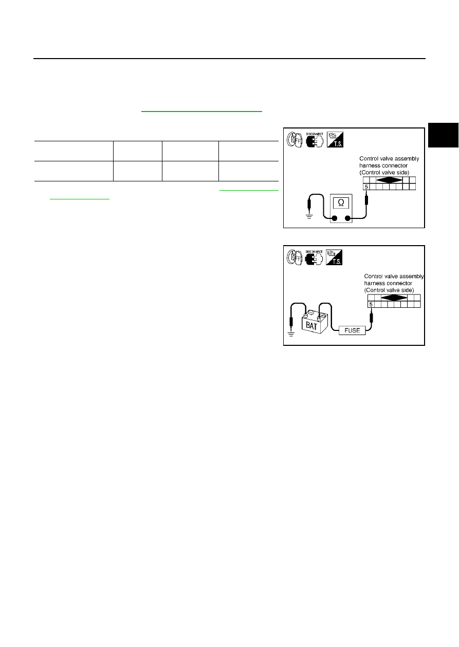
Check resistance between terminal and ground.

5.

If NG, replace control valve assembly. Refer to 

AT-289, "Control

Valve Assembly"

 .

Operation check

Check solenoid valve by listening for its operating sound while
applying battery voltage to the terminal 5 and ground.

Solenoid Valve

Connector No.

Terminal No. 

(Wire color)

Resistance (

(Approx.)

High and low reverse 
clutch solenoid valve

F301

5 (R) - Ground

3 - 9 

SCIA3088E

SCIA3089E

AT-202

DTC P1769 HIGH AND LOW REVERSE CLUTCH SOLENOID VALVE FUNCTION

DTC P1769 HIGH AND LOW REVERSE CLUTCH SOLENOID VALVE FUNCTION

PFP:31940

Description

ECS0087Q

High & low reverse clutch solenoid valve is controlled by the TCM in response to signals sent from the
PNP switch, vehicle speed sensor and accelerator pedal position sensor (throttle position sensor). Gears
will then be shifted to the optimum position.

This is not only caused by electrical malfunction (circuits open or shorted) but also by mechanical mal-
function such as control valve sticking, improper solenoid valve operation.

On Board Diagnosis Logic

ECS0087R

This is an OBD-II self-diagnostic item.

Diagnostic trouble code “HLR/C SOL FNCTN” with CONSULT-II or P1769 without CONSULT-II is
detected under the following conditions.

When TCM detects that actual gear ratio is irregular, and relation between gear position and condition of
ATF pressure switch 6 is irregular during depressing accelerator pedal. (Other than during shift change)

When TCM detects that relation between gear position and condition of ATF pressure switch 6 is irregular
during releasing accelerator pedal. (Other than during shift change)

Possible Cause

ECS0087S

Harness or connectors
(The solenoid and switch circuits are open or shorted.)

High & low reverse clutch solenoid valve 

ATF pressure switch 6

DTC Confirmation Procedure

ECS0087T

CAUTION:

Always drive vehicle at a safe speed.

NOTE:
If “DTC Confirmation Procedure” has been previously conducted, always turn ignition switch “OFF”
and wait at least 10 seconds before conducting the next test.
After the repair, perform the following procedure to confirm the malfunction is eliminated.

 WITH CONSULT-II

1.

Start engine.

2.

Accelerate vehicle to maintain the following condition.
ACCELE POS: 1.5/8 - 2.0/8
Selector lever: “D” position 
Gear position: 2nd 

Þ

 3rd Gear (HLR/C ON/OFF)

3.

Perform step “2” again.

4.

Turn ignition switch to “OFF” position, then perform step “1” to
“3” again.

5.

Check “SELF-DIAG RESULTS” mode for “A/T” with CONSULT-
II. If DTC (P1769) is detected, refer to 

AT-204, "Diagnostic Pro-

cedure"

 .

If DTC (P1767) is detected, go to 

AT-199, "Diagnostic Procedure"

 .

If DTC (P1846) is detected, go to 

AT-233, "Diagnostic Procedure"

 .

 WITH GST

Follow the procedure “With CONSULT-II”.

SAT014K

DTC P1769 HIGH AND LOW REVERSE CLUTCH SOLENOID VALVE FUNCTION

AT-203

D

E

F

G

H

I

J

K

L

M

A

B

AT

Wiring Diagram — AT — HLR/CF

ECS0087U

TCM terminal and data are reference value. Measured between each terminal and ground.

TCWM0096E

Terminal   

No.

Wire 

color

Item

Condition

Data (Approx.)

11

R/L

High & low reverse 
clutch solenoid 
valve

When 
vehicle 
cruises

When the solenoid valve operating [6 km/h (4 MPH) or 
faster in 1st gear or 2nd gear]

More than 2V 

When the solenoid valve is not operating [6 km/h (4 MPH) 
or slower in 1st gear or 3rd, 4th, or 5th gear]

0V

26

G/Y

PSC2
(pressure switch 6)

When high & low reverse clutch solenoid valve “ON”.

0V

When high & low reverse clutch solenoid valve “OFF”.

Battery voltage

AT-204

DTC P1769 HIGH AND LOW REVERSE CLUTCH SOLENOID VALVE FUNCTION

Diagnostic Procedure

ECS0087V

1. 

CHECK INPUT SIGNALS (WITH CONSULT-II)

 With CONSULT-II

1.

Start engine.

2.

Select “ECU INPUT SIGNALS” or “MAIN SIGNALS” in “DATA
MONITOR” mode for “A/T” with CONSULT-II.

3.

Accelerate vehicle in the “D” position (2nd 

Þ

 3rd gear), and con-

firm the ON/OFF actuation of the “ATF PRES SW 6”.

OK or NG

OK

>> GO TO 5.

NG

>> GO TO 3.

2. 

CHECK INPUT SIGNALS (WITHOUT CONSULT-II)

 Without CONSULT-II

1.

Start engine.

2.

Accelerate vehicle in the “D” position (2nd 

Þ

 3rd gear).

OK or NG

OK

>> GO TO 5.

NG

>> GO TO 3.

3. 

CHECK HARNESS BETWEEN TCM AND A/T UNIT ASSEMBLY HARNESS CONNECTOR

1.

Turn ignition switch to “OFF” position.

2.

Disconnect TCM connector.

3.

Check continuity between A/T unit assembly harness connector
and TCM connector.

4.

If OK, check harness for short to ground and short to power.

5.

Reinstall any part removed.

OK or NG

OK

>> GO TO 4.

NG

>> Repair open circuit or short to ground or short to power

in harness or connectors.

PCIA0067E

Solenoid valve

Connector 

No.

Terminal No. 

(Wire color)

Voltage

High and low reverse 
clutch solenoid valve

OFF

F104

26 (G/Y) - Ground

Battery voltage

ON

Approx. 0 V

PCIA0068E

Item

Connector No.

Terminal No. 

(Wire color)

Continuity

TCM

F103

11 (R/L)

Yes

A/T unit assembly harness 
connector

F27

3 (R/L)

TCM

F104

26 (G/Y)

Yes

A/T unit assembly harness 
connector

F26

4 (G/Y)

SCIA3090E


Content   ..  77  78  79  80   ..