Infiniti F50. Manual - part 58


  Index      Infiniti     Infiniti F50 - service repair manual 2006 year


Search            


Content   ..  56  57  58  59   ..


Infiniti F50. Manual - part 58


DTC P0740 TORQUE CONVERTER CLUTCH SOLENOID VALVE

AT-117

D

E

F

G

H

I

J

K

L

M

A

B

AT

DTC P0740 TORQUE CONVERTER CLUTCH SOLENOID VALVE

PFP:31940

Description

ECS0084F

The torque converter clutch solenoid valve is activated, with the gear in D

4

 , D

5

  by the TCM in response

to signals sent from the vehicle speed sensor and accelerator pedal position sensor (throttle position sen-
sor). Torque converter clutch piston operation will then be controlled.

Lock-up operation, however, is prohibited when A/T fluid temperature is too low.

When the accelerator pedal is depressed (less than 1/8) in lock-up condition, the engine speed should not
change abruptly. If there is a big jump in engine speed, there is no lock-up.

CONSULT-II Reference Value

ECS0084G

On Board Diagnosis Logic

ECS0084H

This is an OBD-II self-diagnostic item.

Diagnostic trouble code “TCC SOLENOID/CIRC” with CONSULT-II or P0740 without CONSULT-II is
detected under the following conditions.

When TCM detects an improper voltage drop when it tries to operate the solenoid valve.

When TCM detects as irregular by comparing target value with monitor value.

Possible Cause

ECS0084I

Torque converter clutch solenoid valve

Harness or connectors
(The solenoid circuit is open or shorted.)

DTC Confirmation Procedure

ECS0084J

CAUTION:

Always drive vehicle at a safe speed.

NOTE:
If “DTC Confirmation Procedure” has been previously conducted, always turn ignition switch “OFF”
and wait at least 10 seconds before conducting the next test.
After the repair, perform the following procedure to confirm the malfunction is eliminated.

 WITH CONSULT-II

1.

Turn ignition switch to “ON” position. (Do not start engine.)
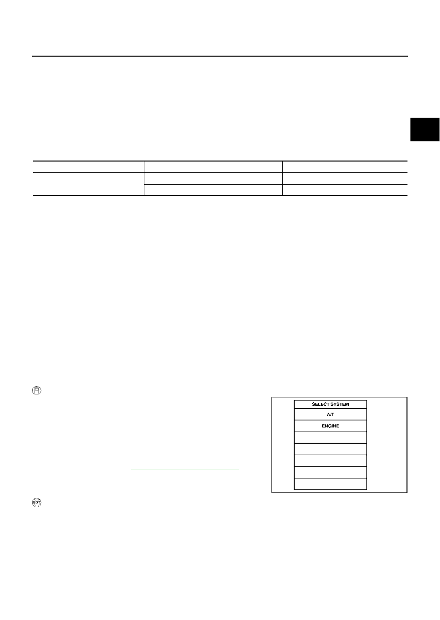
2.

Select “DATA MONITOR” mode for “ENGINE” with CONSULT-II.

3.

Start engine and maintain the following conditions for at least 5
consecutive seconds.
VHCL SPEED SE: 80 km/h (50 MPH) or more
ACCELE POS: 0.5/8 - 1.0/8
SELECTOR LEVER: “D” position 

4.

If DTC is detected go to 

AT-119, "Diagnostic Procedure"

 .

 WITH GST

Follow the procedure “With CONSULT-II”.

Item name

Condition 

Display value (Approx.) (A)

TCC SOLENOID

When perform slip lock-up

0.2 - 0.4

When perform lock-up

0.4 - 0.6

SAT014K

AT-118

DTC P0740 TORQUE CONVERTER CLUTCH SOLENOID VALVE

Wiring Diagram — AT — TCV

ECS0084K

TCM terminal and data are reference value. Measured between each terminal and ground.

TCWM0005E

Terminal   

No.

Wire 

color

Item

Condition

Data (Approx.)

20

Y

TCC solenoid 
valve

When   

vehicle 
cruises

When lock-up

More than 2V 

When not lock-up

0V

DTC P0740 TORQUE CONVERTER CLUTCH SOLENOID VALVE

AT-119

D

E

F

G

H

I

J

K

L

M

A

B

AT

Diagnostic Procedure

ECS0084L

1. 

CHECK TORQUE CONVERTER CLUTCH SOLENOID VALVE CIRCUIT

1.

Turn ignition switch to “OFF” position.

2.

Disconnect A/T unit assembly harness connector at the trans-
mission right side.

3.

Check the resistance between terminal and ground.

OK or NG

OK >> GO 

TO 

4.

NG

>> GO TO 2.

2. 

CHECK TERMINAL CORD ASSEMBLY

1.

Remove oil pan. Refer to 

AT-289, "Control Valve Assembly"

 .

2.

Disconnect A/T unit assembly harness connector and control valve assembly harness connector.

3.

Check continuity between A/T unit assembly harness connector
and control valve assembly harness connector.

4.

If OK, check harness for short to ground and short to power.

5.

Reinstall any part removed.

OK or NG

OK

>> GO TO 3.

NG

>> Repair open circuit or short to ground or short to power in harness or connectors.

3. 

CHECK VALVE RESISTANCE

Check valve resistance

Refer to 

AT-120, "Component Inspection"

 .

OK or NG

OK >> GO 

TO 

4.

NG

>> Replace the control valve assembly. Refer to 

AT-289, "Control Valve Assembly"

 .

Solenoid valve

Connector No.

Terminal No. 

(Wire color)

Resistance (Approx.) 

Torque converter clutch 
solenoid valve

F27

8 (Y) - Ground

3 - 9 

SCIA1830E

Item

Connector No.

Terminal No. (Wire color)

Continuity

A/T unit assembly 
harness connector

F27

8 (R/B)

Yes

Control valve assem-
bly harness connec-
tor

F301

11 (R/B)

SCIA3060E

AT-120

DTC P0740 TORQUE CONVERTER CLUTCH SOLENOID VALVE

4. 

CHECK POWER SOURCE CIRCUIT

1.

Turn ignition switch to “OFF” position.

2.

Disconnect TCM connector.

3.

Check continuity between A/T unit assembly harness connector
and TCM connector.

4.

If OK, check harness for short to ground and short to power.

5.

Reinstall any part removed.

OK or NG

OK

>> GO TO 5.

NG

>> Repair open circuit or short to ground or short to power in harness or connectors.

5. 

CHECK DTC

Perform “DTC Confirmation Procedure”. Refer to 

AT-117, "DTC Confirmation Procedure"

 .

OK or NG

OK

>> INSPECTION END

NG

>> GO TO 6.

6. 

PERFORM TCM INSPECTION

1.

Perform TCM input/output signal inspection.

2.

If NG, recheck TCM pin terminals for damage or loose connection with harness connector.

OK or NG

OK

>> INSPECTION END

NG

>> Repair or replace damaged parts.

Component Inspection

ECS00A1I

TORQUE CONVERTER CLUTCH SOLENOID VALVE
Resistance check

1.

Turn ignition switch “OFF”.

2.

Remove oil pan. Refer to 

AT-289, "Control Valve Assembly"

 .

3.

Disconnect control valve assembly harness connector.

4.

Check resistance between terminal and ground.

5.

If NG, replace control valve assembly. Refer to 

AT-289, "Control

Valve Assembly"

 .

Item

Connector No.

Terminal No. (Wire color)

Continuity

TCM

F103

20 (Y)

Yes

A/T unit assembly 
harness connector

F27

8 (Y)

SCIA1831E

Solenoid Valve

Connector No.

Terminal No. 

(Wire color)

Resistance (

(Approx.)

Torque converter clutch 
solenoid valve

F301

11 (BR) - Ground

3 - 9 

SCIA3061E


Content   ..  56  57  58  59   ..