Infiniti F50. Manual - part 50
TROUBLE DIAGNOSIS
AT-85
D
E
F
G
H
I
J
K
L
M
A
B
AT
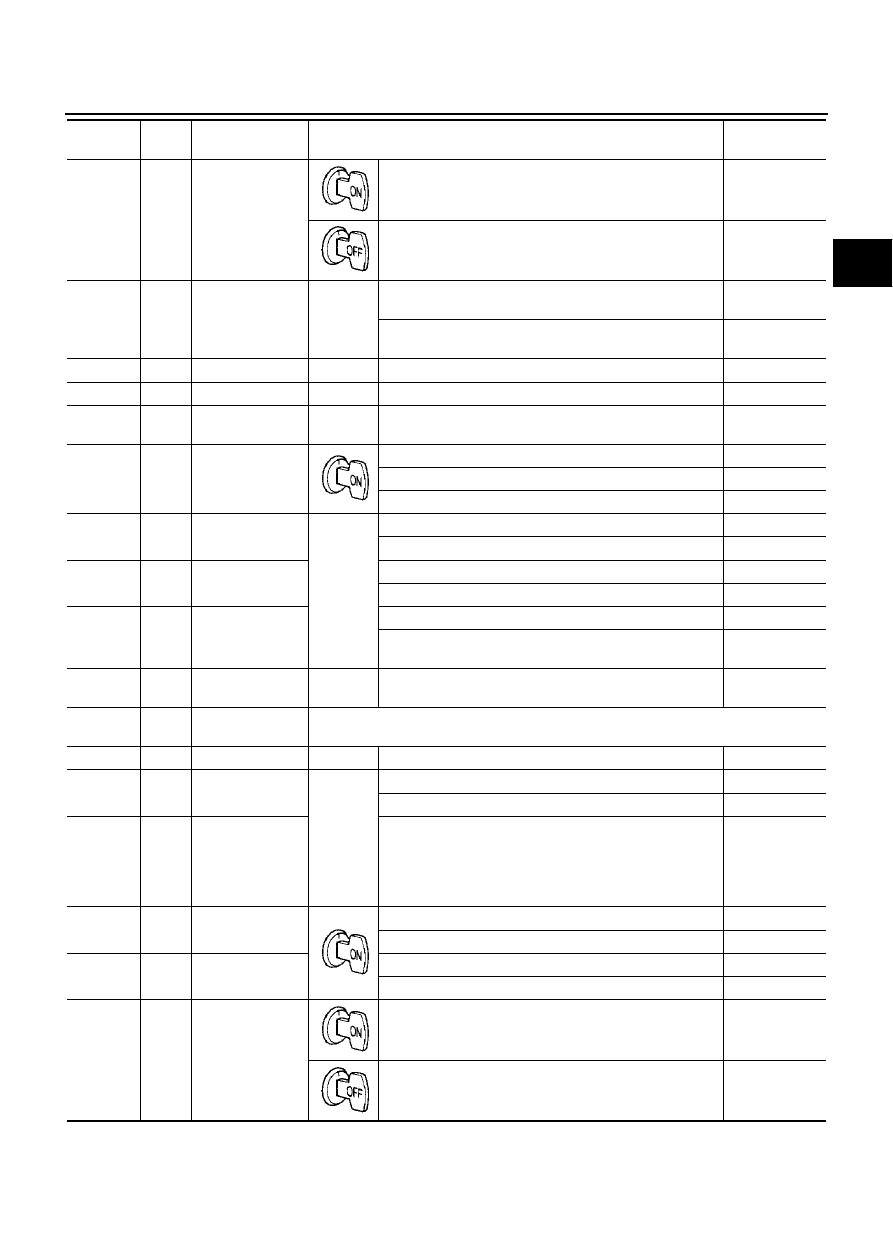
12
Y/R
Power supply
(out)
–
Battery voltage
–
0V
13
W/L
Low coast brake
solenoid valve
When
vehicle
cruises
When the solenoid valve is operating (when running in M1-
1 gear or M2-2 gear)
Battery voltage
When the solenoid valve is not operating (when running in
“D”)
0V
14
B
Ground
–
–
–
15
B/W
SEL4
–
–
–
16
W/G
SEL1 (pressure
switch 2)
–
–
–
17
Y/B
Fluid temperature
sensor 2
When ATF temperature about 0
°
C (32
°
F)
2.2V
When ATF temperature about 20
°
C (68
°
F)
1.7V
When ATF temperature about 80
°
C (176
°
F)
0.45V
19
R
Front brake sole-
noid valve
When
vehicle
cruises
When the solenoid valve is operating (other than 4th gear)
More than 2V
When the solenoid valve is not operating (4th gear)
0V
20
Y
TCC solenoid
valve
When lock-up
More than 2V
When not lock-up
0V
21
G
Direct clutch sole-
noid valve
When the solenoid valve is operating (1st gear or 5th gear)
More than 2V
When the solenoid valve is not operating (2nd gear, 3rd
gear, or 4th gear)
0V
22
P/B
SEL2 (pressure
switch 5)
–
–
–
23
PU/W
K-line (CONSULT-
II signal)
The terminal is connected to the data link connector for CONSULT-II.
24
B
Ground
–
–
–
26
G/Y
PSC2 (pressure
switch 6)
When
vehicle
cruises
When high and low reverse clutch solenoid valve “ON”.
0V
When high and low reverse clutch solenoid valve “OFF”.
Battery voltage
27
Y/B
Vehicle speed
sensor A/T (revo-
lution sensor)
When moving at 20 km/h (12 MPH), use the CONSULT-II
pulse frequency measuring function.
CAUTION:
Connect the data link connector to the vehicle-side
diagnosis connector.
185 (Hz)
30
R/W
PNP switch 1
Selector lever in “P” position.
Battery voltage
Selector lever in “N” position.
Less than 2.5V
31
OR
PNP switch 2
Selector lever in “P” position.
Battery voltage
Selector lever in “D” position.
Less than 2.5V
33
G/R
Power supply
–
Battery voltage
–
0V
Terminal
No.
Wire
color
Item
Condition
Data (Approx.)