Infiniti F50. Manual - part 9


  Index      Infiniti     Infiniti F50 - service repair manual 2006 year


Search            


Content   ..  7  8  9  10   ..


Infiniti F50. Manual - part 9


AUTOMATIC SPEED CONTROL DEVICE (ASCD)

ACS-29

[ASCD]

C

D

E

F

G

H

I

J

L

M

A

B

ACS

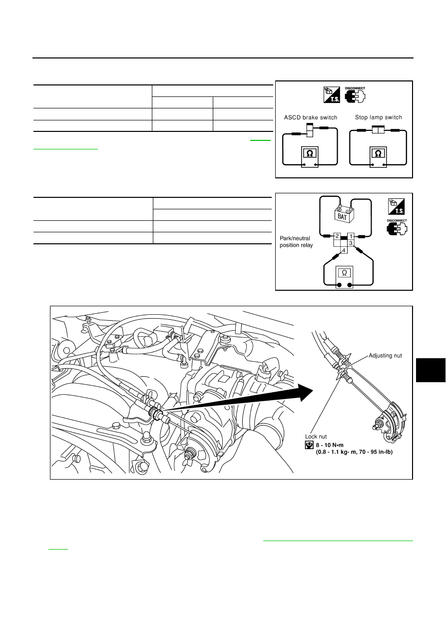
Electrical Component Inspection

EKS003OG

ASCD BRAKE SWITCH AND STOP LAMP SWITCH

Check each switch after adjusting brake pedal — refer to 

BR-6,

"BRAKE PEDAL"

 .

PARK/NEUTRAL POSITION RELAY

ASCD Wire Adjustment

EKS003OH

CAUTION:

Be careful not to twist ASCD wire when removing it.

Do not tense ASCD wire excessively during adjustment.

Adjust the tension of ASCD wire in the following manner.
1.

Loosen lock nut and adjusting nut.

2.

Make sure that accelerator wire is properly adjusted. Refer to 

ACC-2, "ACCELERATOR CONTROL SYS-

TEM"

 .

3.

Tighten adjusting nut just until throttle drum starts to move.

4.

Loosen adjusting nut again 1/2 to 1 turn.

5.

Tighten lock nut to specified torque holding the adjusting nut.

Condition

Continuity

ASCD brake switch

Stop lamp switch

When brake pedal is depressed

No

Yes

When brake pedal is released

Yes

No

PBIC0224E

Continuity

Between terminals 3 and 4

Battery voltage supply

No

Battery voltage not supply

Yes

PKIA2378E

PBIC0226E

ACS-30

[ASCD]

SERVICE DATA AND SPECIFICATIONS (SDS)

SERVICE DATA AND SPECIFICATIONS (SDS)

PFP:00030

Standard and Limit

EKS003OI

Tightening torque

EKS003OJ

                                                                                                                                                                                  Unit: N·m (kg-m, ft-lb)
                                                                                                                                                                                  Unit: N·m (kg-m, in-lb)*

Turning back of ASCD cable adjusting nut 

1/2 - 1.0 turns (From position throttle drum just starts to move)

ACSD cable lock nut

                                 8 - 10 (0.8 - 1.1, 70 - 95)*

ASCD actuator

Bolt

                             4.4 - 5.8 (0.45 -  0.59, 39 - 51)*

Nut

                              10.8 - 13.7 (1.1 - 1.3, 8 - 10)

ASCD control unit

                             2.9 - 3.9 (0.30 - 0.39, 26 - 34)*

PRECAUTIONS

ACS-31

[ICC]

C

D

E

F

G

H

I

J

L

M

A

B

ACS

[ICC]

PRECAUTIONS

PFP:00001

Precautions for Supplemental Restraint System (SRS) “AIR BAG” and “SEAT 
BELT PRE-TENSIONER”

EKS006S9

The Supplemental Restraint System such as “AIR BAG” and “SEAT BELT PRE-TENSIONER”, used along
with a front seat belt, helps to reduce the risk or severity of injury to the driver and front passenger for certain
types of collision. This system includes seat belt switch inputs and dual stage front air bag modules. The SRS
system uses the seat belt switches to determine the front air bag deployment, and may only deploy one front
air bag, depending on the severity of a collision and whether the front occupants are belted or unbelted.
Information necessary to service the system safely is included in the SRS and SB section of this Service Man-
ual.

WARNING:

To avoid rendering the SRS inoperative, which could increase the risk of personal injury or death
in the event of a collision which would result in air bag inflation, all maintenance must be per-
formed by an authorized NISSAN/INFINITI dealer.

Improper maintenance, including incorrect removal and installation of the SRS, can lead to per-
sonal injury caused by unintentional activation of the system. For removal of Spiral Cable and Air
Bag Module, see the SRS section.

Do not use electrical test equipment on any circuit related to the SRS unless instructed to in this
Service Manual. SRS wiring harnesses can be identified by yellow and/or orange harnesses or
harness connectors.

Precautions for ICC System Service

EKS003S3

Do not look straight into the laser beam discharger when adjusting laser beam aiming.

Turn the ON/OFF switch OFF in conditions similar to driving, suchlike Free rollers or a chassis dynamom-
eter.

Do not use the ICC sensor removing from vehicle, disassemble, or remodel the sensor.

Erase DTCs when replacing parts of ICC system, then check the operation of ICC system after adjusting
laser beam aiming if necessary.

Wiring Diagrams and Trouble Diagnosis 

EKS003S4

When you read wiring diagrams, refer to the followings:

Refer to 

GI-13, "How to Read Wiring Diagrams"

  in GI section

Refer to 

PG-2, "POWER SUPPLY ROUTING"

  for power distribution circuit in PG section

When you perform trouble diagnosis, refer to the followings:

Refer to 

GI-10, "HOW TO FOLLOW TEST GROUPS IN TROUBLE DIAGNOSES"

  in GI section

Refer to 

GI-26, "How to Perform Efficient Diagnosis for an Electrical Incident"

  in GI section

ACS-32

[ICC]

PREPARATION

PREPARATION

PFP:00002

Special Service Tool

EKS003ON

The actual shapes of Kent-Moore tools may differ from those of special service tools illustrated here.

Tool number 
(Kent – Moore No. )
Tool name

Description

KV99110100
(J-45718)
ICC target board

Laser beam aiming adjustment

PKIA0358J


Content   ..  7  8  9  10   ..