Infiniti F50. Manual - part 5
 

  Index      Infiniti     Infiniti F50 - service repair manual 2006 year


Search            


Content   ..  3  4  5  6   ..


Infiniti F50. Manual - part 5


AUTOMATIC SPEED CONTROL DEVICE (ASCD)

ACS-13

[ASCD]

C

D

E

F

G

H

I

J

L

M

A

B

ACS

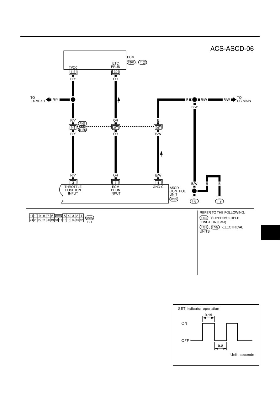
FIG. 6

Fail-Safe System

EKS003OB

DESCRIPTION

When the fail-safe system senses a malfunction, it deactivates
ASCD operation. The SET indicator in the combination meter will
then flash.

TKWM0444E

PBIC0201E

ACS-14

[ASCD]

AUTOMATIC SPEED CONTROL DEVICE (ASCD)

MALFUNCTION DETECTION CONDITIONS

CONSULT-II Inspection Procedure

EKS003OC

1.

Turn ignition switch OFF.

2.

Connect CONSULT-II and CONSULT-ll CONVERTER to data
link connector.

3.

Turn ignition switch ON.

4.

Turn MAIN (CRUISE) switch ON.

5.

Touch START(NISSAN BASED VHCL) (on CONSULT-II dis-
play).

6.

Touch ASCD.
If “ASCD” is not indicated, go to 

GI-38, "CONSULT-II Data Link

Connector (DLC) Circuit"

 .

7.

Touch SELF-DIAG RESULTS.

Detection conditions

ASCD operation during malfunc-

tion detection

●

ASCD steering (RESUME/ACCEL, CANCEL, SET/COAST) switch is stuck.

●

Vacuum motor ground circuit or power circuit is open or shorted.

●

Air valve ground circuit or power circuit is open or shorted.

●

Release valve ground circuit or power circuit is open or shorted.

●

Vehicle speed sensor is faulty.

●

ASCD control unit internal circuit is malfunctioning.

●

ASCD is deactivated.

●

Vehicle speed memory is can-
celed.

●

ASCD brake switch or stop lamp switch is faulty.

●

ASCD is deactivated.

●

Vehicle speed memory is not 
canceled.

PBIC0202E

SKIA3098E

PEL041P

AUTOMATIC SPEED CONTROL DEVICE (ASCD)

ACS-15

[ASCD]

C

D

E

F

G

H

I

J

L

M

A

B

ACS

●

Self-diagnostic results are shown on display.
Refer to 

ACS-15, "CONSULT-II Self-diagnostic Results"

  table.

8.

Touch DATA MONITOR.

●

Touch START.

●

Data monitor results are shown on display.
Refer to 

ACS-16, "CONSULT-II Data Monitor"

  table.

For further information, read the CONSULT-II Operation Manual.

CONSULT-II Self-diagnostic Results

EKS003OD

PFA021B

PEL043P

PEL811S

Diagnostic item

Description

Repair/Check order

NO DTC IS DETECTED.
FURTHER TESTING
MAY BE REQUIRED.

●

Even if no malfunction is indicated, further testing may be 
required as far as the customer complains.

—

POWER SUPPLY-VALVE

●

The power supply circuit for the ASCD pump is open. (An 
abnormally high voltage is entered.)

ASCD PUMP CIRCUIT CHECK 

ACS-24

VACUUM PUMP

●

The vacuum motor circuit is open or shorted. (An abnor-
mally high or low voltage is entered.)

ASCD PUMP CIRCUIT CHECK 

ACS-24

AIR VALVE

●

The air valve circuit is open or shorted. (An abnormally 
high or low voltage is entered.)

ASCD PUMP CIRCUIT CHECK 

ACS-24

RELEASE VALVE

●

The release valve circuit is open or shorted. (An abnor-
mally high or low voltage is entered.)

ASCD PUMP CIRCUIT CHECK 

ACS-24

VHCL SP·S/FAILSAFE

●

The vehicle speed sensor is malfunctioning.

VEHICLE SPEED SENSOR 
CHECK 

ACS-23

CONTROL UNIT

●

The ASCD control unit is malfunctioning.

Replace ASCD control unit

BRAKE SW/STOP/L SW

●

The brake switch or stop lamp switch circuit is malfunc-
tioning.

ASCD BRAKE/STOP LAMP 
SWITCH CHECK 

ACS-20

ACS-16

[ASCD]

AUTOMATIC SPEED CONTROL DEVICE (ASCD)

CONSULT-II Data Monitor

EKS003OE

COMMAND SW

●

The steering switch (SET/COAST switch, RESUME/
ACCEL switch or CANCEL switch) is malfunctioning.

ASCD STEERING SWITCH 
CHECK 

ACS-22

ECM

●

The ECM is malfunctioning.

ECM SIGNAL CHECK 

ACS-27

Diagnostic item

Description

Repair/Check order

Monitored item

Description

BRAKE SW

●

Indicates [ON/OFF] condition of the brake switch and park/neutral position relay.

AT OD MONITOR

●

Indicates [ON/OFF] condition of A/T O/D (shift solenoid valve A).

STOP LAMP SW

●

Indicates [ON/OFF] condition of the stop lamp switch.

MAIN SW

●

Indicates [ON/OFF] condition of MAIN (CRUISE) switch.

SET SW

●

Indicates [ON/OFF] condition of the SET switch.

RESUME/ACC SW

●

Indicates [ON/OFF] condition of the RESUME/ACCEL switch.

CANCEL SW

●

Indicates [ON/OFF] condition of the CANCEL.

VHCL SPEED SE

●

The present vehicle speed computed from the vehicle speed sensor signal is displayed.

SET VHCL SPD

●

The preset vehicle speed is displayed.

VACUUM PUMP

●

The operation time of the vacuum pump is displayed.

AIR VALVE

●

The operation time of the air valve is displayed.

PW SUP-VALVE

●

Indicates [ON/OFF] condition of the circuit for the air valve and the release valve.

CRUISE LAMP

●

Indicates [ON/OFF] condition of the set lamp.

MAIN LAMP

●

Indicates [ON/OFF] condition of cruise lamp.

A/T·OD CANCEL

●

Indicates [ON/OFF] condition of the OD cancel.

FAIL SAFE·LOW

●

The fail-safe (LOW) circuit function is displayed.

FAIL SAFE·SPD 

●

The fail-safe (SPEED) circuit function is displayed.

TCS MONITOR 

●

Indicates [ON/OFF] condition of TCS.

THRTL POS SEN

●

The voltage of throttle position sensor is displayed.

R/LORD ESTMT

●

The present road/load computed by ASCD control unit is displayed.


Content   ..  3  4  5  6   ..