Infiniti I35 (A33). Manual - part 436
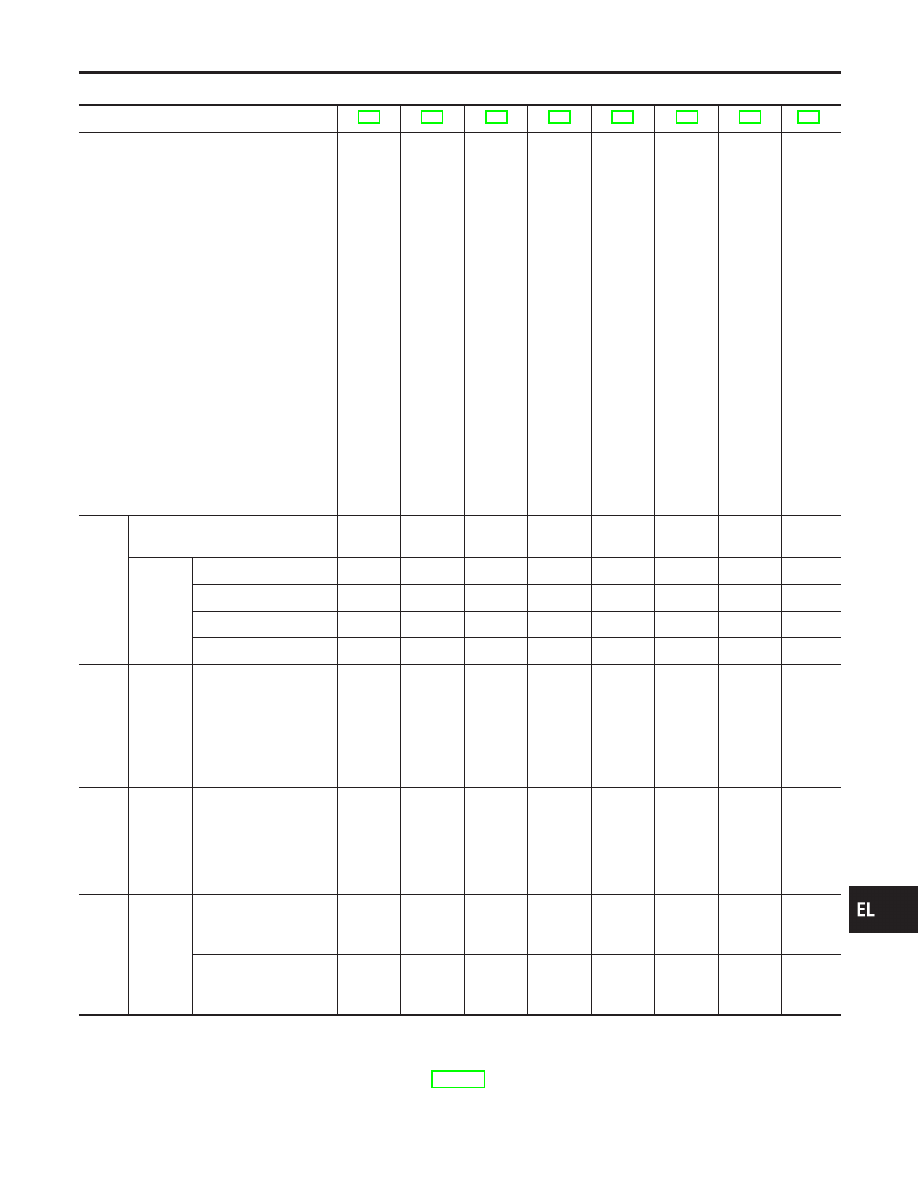
SYMPTOM CHART
NHEL0123S02
REFERENCE PAGE (EL-
)
SYMPTOM
PRELIMINAR
Y
CHECK
POWER
SUPPL
Y
AND
GROUND
CIRCUIT
CHECK
DOOR,
HOOD
AND
TRUNK
ROOM
LAMP
SWITCH
CHECK
SECURITY
INDICA
T
O
R
LAMP
CHECK
DOOR
KEY
CYLINDER
SWITCH
CHECK
DOOR
LOCK/UNLOCK
SWITCH
CHECK
VEHICLE
SECURITY
HORN
AND
HEADLAMP
ALARM
CHECK
Check
“REMOTE
KEYLESS
ENTR
Y
SYSTEM”.
1
Vehicle security indicator does not
illuminate for 30 seconds.
X
X
X
V
ehicle
security
system
cannot
be
set
by
....
All items
X
X
X
Door outside key
X
X
Lock/unlock switch
X
X
Keyfob
X
X
2
*1
V
ehicle
security
system
does
not
alarm
when
...
One of the door is
opened
X
X
3
V
ehicle
security
alarm
does
not
activate.
Horn or headlamp
alarm
X
X
X
4
V
ehicle
security
system
cannot
be
canceled
by
....
Door outside key
X
X
Keyfob
X
X
X : Applicable
*1: Make sure the system is in the armed phase.
Before starting trouble diagnoses above, perform preliminary
check, EL-344.
Symptom numbers in the symptom chart correspond with those of
preliminary check.
GI
MA
EM
LC
EC
FE
AT
AX
SU
BR
ST
RS
BT
HA
SC
IDX
VEHICLE SECURITY (THEFT WARNING) SYSTEM
Trouble Diagnoses (Cont’d)
EL-345