Infiniti I35 (A33). Manual - part 138
 

  Index      Infiniti     Infiniti I35 (A33) - service repair manual 2004 year


Search            


Content   ..  136  137  138  139   ..


Infiniti I35 (A33). Manual - part 138


Inspection 4 Pressure Sensor and The Circuit
Between Pressure Sensor and VDC/TCS/ABS
Control Unit

=NHBR0273

Inspection procedure

1

SELF-DIAGNOSIS RESULT CHECK 1

Check the self-diagnosis results.

MTBL1266

Is “PRESS SEN CIRCUIT” indicated in the self-diagnosis results?

©

GO TO 2.

2

SELF-DIAGNOSIS RESULT CHECK 2

1. Disconnect connectors of the pressure sensor and the VDC/TCS/ABS control unit, and connect them again correctly.
2. Perform the VDC/TCS/ABS control unit self-diagnosis again.

Is inspection result OK?

OK

©

Repair or replace the poorly connected connector, then perform the self-diagnosis again.

NG

©

GO TO 3.

3

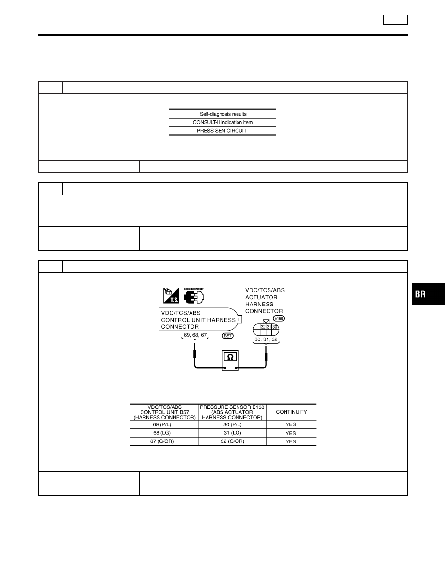
PRESSURE SENSOR CIRCUIT INSPECTION

1. Disconnect connectors of the pressure sensor and the VDC/TCS/ABS control unit.

SBR188F

2. Check for continuity between the VDC/TCS/ABS control unit (harness connector B57) and the pressure sensor (har-

ness connector E168).

MTBL1383

Is inspection result OK?

OK

©

GO TO 4.

NG

©

Repair or replace the disconnected harness.

GI

MA

EM

LC

EC

FE

AT

AX

SU

ST

RS

BT

HA

SC

EL

IDX

TROUBLE DIAGNOSES FOR SELF-DIAGNOSTIC ITEMS

VDC

Inspection 4 Pressure Sensor and The Circuit Between Pressure Sensor and VDC/TCS/ABS Control Unit

BR-137

4

PRESSURE SENSOR INSPECTION

Check the “PRESS SENSOR” value in “DATA MONITOR”.

MTBL1268

Is inspection result OK?

OK

©

Perform the VDC/TCS/ABS control unit self-diagnosis again.

NG

©

Pressure sensor malfunction. Replace the ABS actuator (with the pressure sensor).

TROUBLE DIAGNOSES FOR SELF-DIAGNOSTIC ITEMS

VDC

Inspection 4 Pressure Sensor and The Circuit Between Pressure Sensor and VDC/TCS/ABS Control Unit (Cont’d)

BR-138

Inspection 5 Steering Angle Sensor and The
Circuit Between Steering Angle Sensor and
VDC/TCS/ABS

=NHBR0274

Inspection procedure

1

SELF-DIAGNOSIS RESULT CHECK 1

Check the self-diagnosis results.

MTBL1269

Perform inspection 15.
Refer to Inspection 15 CAN Communication Circuit, VDC/TCS/ABS Control Unit and Steering Angle Sensor, BR-156.

Is “ST ANG SEN CIRCUIT” indicated in the self-diagnosis results?

©

GO TO 2.

2

SELF-DIAGNOSIS RESULT CHECK 2

1. Repair or replace the poorly connected connector.
–

Check the connector housing for disconnect, loose, bent and collapse terminals.
If any malfunction are detected, repair or replace the applicable part.

2. Perform the VDC/TCS/ABS control unit self-diagnosis again.

Is inspection result OK?

OK

©

INSPECTION END

NG

©

GO TO 3.

3

STEERING ANGLE SENSOR CURCUIT CHECK

1. Disconnect the VDC/TCS/ABS control unit connector B57 and the steering angle sensor connector M218.

SBR190F

2. Check for continuity between the VDC/TCS/ABS control unit (harness connector B57) and the steering angle sensor

(harness connector M218).

MTBL1384

Is inspection result OK?

OK

©

GO TO 4.

NG

©

Repair or replace the disconnected harness.

GI

MA

EM

LC

EC

FE

AT

AX

SU

ST

RS

BT

HA

SC

EL

IDX

TROUBLE DIAGNOSES FOR SELF-DIAGNOSTIC ITEMS

VDC

Inspection 5 Steering Angle Sensor and The Circuit Between Steering Angle Sensor and VDC/TCS/ABS

BR-139

4

DATA MONITOR CHECK

Perform the “STR ANGLE SIG” value in “DATA MONITOR” and check that it is in normal condition.

MTBL1271

Is inspection result OK?

OK

©

Perform the VDC/TCS/ABS control unit self-diagnosis again.

NG

©

Replace the spiral cable (with the steering angle sensor) and adjust the neutral position
of steering angle sensor. Adjustment of Neutral Position of Steering Angle Sensor,
BR-93.

TROUBLE DIAGNOSES FOR SELF-DIAGNOSTIC ITEMS

VDC

Inspection 5 Steering Angle Sensor and The Circuit Between Steering Angle Sensor and VDC/TCS/ABS (Cont’d)

BR-140


Content   ..  136  137  138  139   ..