Infiniti I30 (A33). Manual - part 590


  Index      Infiniti     Infiniti I30 (A33) - service repair manual 2001 year


Search            


Content   ..  588  589  590  591   ..


Infiniti I30 (A33). Manual - part 590


SST472A

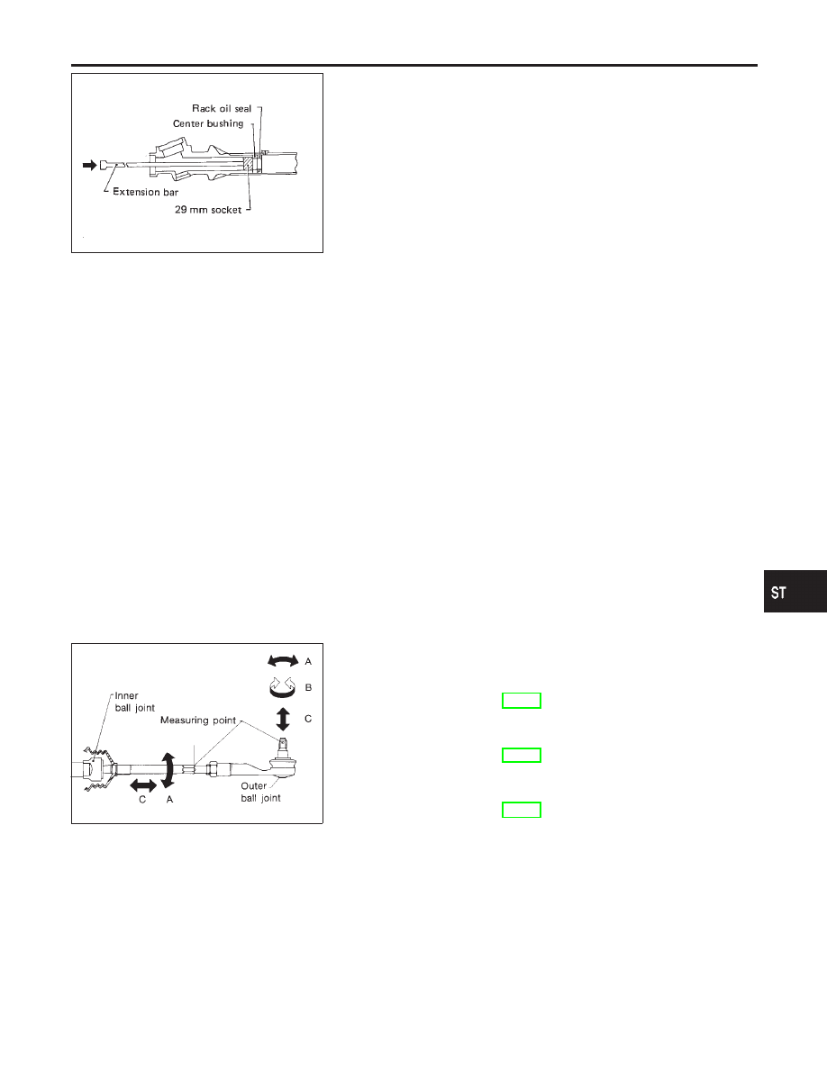
10. Remove center bushing and rack oil seal using tape wrapped

socket and extension bar.

Do not scratch inner surfaces of pinion housing.

Inspection

NHST0024

Thoroughly clean all parts in cleaning solvent or Genuine NISSAN
PSF II or equivalent. Blow dry with compressed air, if available.

BOOT

NHST0024S01

I

Check condition of boot. If cracked excessively, replace it.

I

Check boots for accumulation of power steering fluid.

RACK

NHST0024S02

Thoroughly examine rack gear. If damaged, cracked or worn,
replace it.

GEAR SUB-ASSEMBLY

NHST0024S03

I

Check pinion gear. If it is worn or damaged, replace as a gear
sub-assembly.

I

Manually spin bearing. If torque variations or free play are
noted, replace as a gear sub-assembly.

GEAR HOUSING CYLINDER

NHST0024S04

Check gear housing cylinder bore for scratches or other damage.
Replace if necessary.

SST468C

TIE-ROD OUTER AND INNER SOCKETS

NHST0024S05

I

Check ball joints for swinging force.

Tie-rod outer and inner ball joints swinging force “A”:

Refer to SDS, ST-30.

I

Check ball joint for rotating torque.

Tie-rod outer ball joint rotating torque “B”:

Refer to SDS, ST-30.

I

Check ball joints for axial end play.

Tie-rod outer and inner ball joints axial end play “C”:

Refer to SDS, ST-30.

I

Check condition of dust cover. If cracked excessively, replace
outer tie-rod.

GI

MA

EM

LC

EC

FE

AT

AX

SU

BR

RS

BT

HA

SC

EL

IDX

POWER STEERING GEAR AND LINKAGE

Disassembly (Cont’d)

ST-19

SST083B

Assembly

NHST0025

1.

Using a heat gun, heat new teflon rack seal ring to approxi-
mately 40°C (104°F). Then place it onto rack.

SST885BB

2.

Using Tool, compress rack seal ring securely onto rack.

Always insert Tool from the rack gear side.

SST201A

3.

Insert new rack oil seal.

I

Place plastic film into rack oil seal to prevent damage by
rack teeth.

I

Do not forget to remove plastic film after rack oil seal is
positioned properly.

I

Make sure lips of rack oil seal face each other.

SST863C

4.

Install center bushing and rack oil seal with rack assembly.

SST321B

5.

Insert rack oil seal and end cover assembly to rack. Then
tighten end cover assembly.

POWER STEERING GEAR AND LINKAGE

Assembly

ST-20

SST073B

6.

Fasten end cover assembly to gear housing by staking.

SST086BA

7.

Set rack gear in neutral position.

Rack stroke “S”:

Refer to SDS, ST-30.

SST864C

8.

Install adjustment shims and O-rings to gear sub-assembly.

I

Install the same number of adjustment shims as before,
regardless of whether or not gear sub-assembly is replaced.

I

Discard old O-rings; replace with new ones.

9.

Tighten gear subassembly securing bolts to specified tighten-
ing torque.

SST865C

10. Ensure that the rack is centered. Install rear cover cap so that

its protrusion is positioned as shown in figure.

SST087B

11. Install diaphragm spring into gear housing.

I

Always install retainer, spring washer and diaphragm spring in
that order.

I

Make sure convex end (painted white) of diaphragm spring
faces outward when installing.

12. Install spring seat retainer spring and adjusting screw tempo-

rarily.

GI

MA

EM

LC

EC

FE

AT

AX

SU

BR

RS

BT

HA

SC

EL

IDX

POWER STEERING GEAR AND LINKAGE

Assembly (Cont’d)

ST-21

SST866C

13. Install lock plate to rack.
a.

Temporarily install spacer ring to rack.

Discard old spacer ring; replace with a new one.
b.

Install lock plate to inner socket.

Discard old lock plate; replace with a new one.
c.

Apply a coat of locking sealant to inner socket threads. Screw
inner socket into rack and tighten to specified torque.

d.

Clinch lock plate at rack groove location (at two points).

e.

Install spacer ring to lock plate as shown in the Figure at left.

Be careful not to damage spacer ring during installation

SST867C

14. Tighten outer socket lock nut.

Tie-rod length “L”:

Refer to SDS, ST-30.

SST086BA

15. Measure rack stroke.

Rack stroke “S”:

Refer to SDS, ST-30.

SST967A

16. Before installing boot, coat the contact surfaces between boot

and tie-rod with grease.

SST868C

17. Install boot bands.

I

Securely install boot band to boot groove and clinch the root
section of the trapezoidal area.

I

Make sure that there is a clearance of 3.5 mm (0.138 in) or less
at the clinched section of the boot band. Refer to the Figure at
left.

POWER STEERING GEAR AND LINKAGE

Assembly (Cont’d)

ST-22


Content   ..  588  589  590  591   ..