Infiniti I30 (A33). Manual - part 547
SLC116B
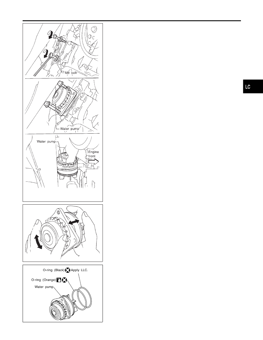
9.
Tighten M8 bolts by turning half turn alternately until they reach
timing chain rear case.
I
In order to prevent damages to water pump or timing chain rear
case, do not tighten one bolt continuously. Always turn each
bolt half turn each time.
10. Lift up water pump and remove it.
I
When lifting up water pump, do not allow water pump gear to
hit timing chain.
SLC943A
INSPECTION
NHLC0019
1.
Check for badly rusted or corroded body assembly.
2.
Check for rough operation due to excessive end play.
SLC244B
INSTALLATION
NHLC0020
1.
Apply engine oil and coolant to O-rings as shown in the figure.
GI
MA
EM
EC
FE
AT
AX
SU
BR
ST
RS
BT
HA
SC
EL
IDX
ENGINE COOLING SYSTEM
Water Pump (Cont’d)
LC-13