Infiniti I30 (A33). Manual - part 539


  Index      Infiniti     Infiniti I30 (A33) - service repair manual 2001 year


Search            


Content   ..  537  538  539  540   ..


Infiniti I30 (A33). Manual - part 539


RHA143EA

I

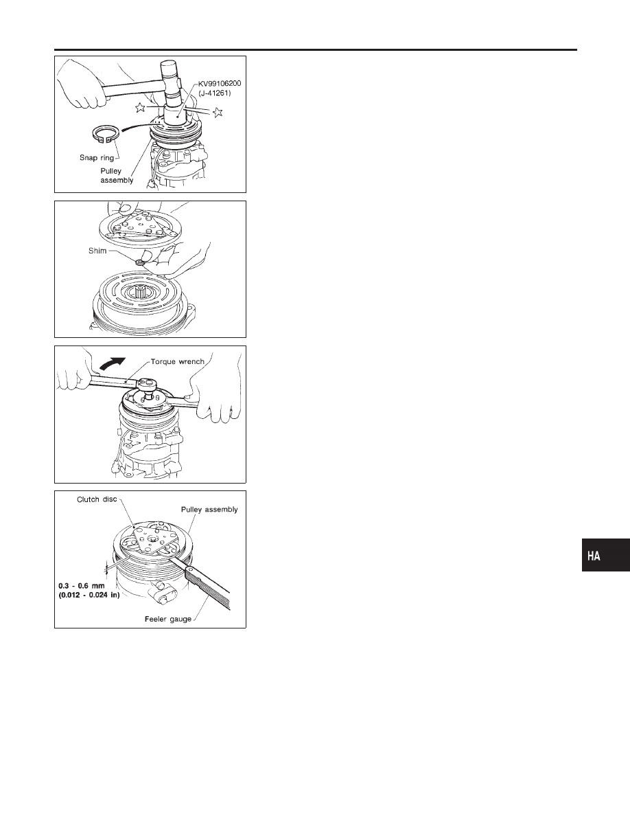
Install the pulley assembly using the installer and a hand
press, and then install the snap ring using snap ring pliers.

RHA127F

I

Install the clutch disc on the drive shaft, together with the
original shim(s). Press the clutch disc down by hand.

RHA086E

I

Using the holder to prevent clutch disc rotation, tighten the bolt
to 14 N·m (1.4 kg-m, 10 ft-lb) torque.
After tightening the bolt, check that the pulley rotates
smoothly.

RHA087E

I

Check clearance around the entire periphery of clutch disc.

Disc-to-pulley clearance:

0.3 - 0.6 mm (0.012 - 0.024 in)

If the specified clearance is not obtained, replace adjusting
spacer and readjust.

Break-in Operation

NHHA0234S01

When replacing compressor clutch assembly, always carry out the
break-in operation. This is done by engaging and disengaging the
clutch about thirty times. Break-in operation raises the level of
transmitted torque.

GI

MA

EM

LC

EC

FE

AT

AX

SU

BR

ST

RS

BT

SC

EL

IDX

SERVICE PROCEDURE

Compressor Clutch (Cont’d)

HA-115

Heater Unit (Heater Core)

REMOVAL

NHHA0249

RHA420H

1.

Drain the cooling system. Refer to MA-14, “Changing Engine
Coolant”.

2.

Disconnect the two heater hoses from inside the engine com-
partment.

3.

Remove the Blower and cooling unit. Refer to HA-117.

4.

Remove the steering member assembly. Refer to BT-28, “Instru-
ment Panel Assembly”.

5.

Remove the heater unit.

6.

Remove the heater core.

INSTALLATION

NHHA0250

Installation is basically the reverse order of removal.
When filling radiator with coolant, refer to MA-14, “Changing
Engine Coolant”.

SERVICE PROCEDURE

Heater Unit (Heater Core)

HA-116

Blower and Cooling Unit (A/C Evaporator)

REMOVAL

NHHA0251

RHA422H

RHA421H

1.

Discharge the A/C system. Refer to HA-107.

2.

Disconnect the two refrigerant lines from the engine compart-
ment.
Cap the A/C lines to prevent moisture from entering the sys-
tem.

3.

Remove the glove box and mating trim. Refer to BT-28, “Instru-
ment Panel Assembly”.

4.

Disconnect the thermal amp. connector.

5.

Disconnect the intake sensor connector.

6.

Disconnect the fan control amp. and blower motor connector.

7.

Remove the blower and cooling unit.

8.

Separate the blower and cooling unit case, and remove the
evaporator.

9.

Remove the three bolts and then remove the motor from the
blower case.

INSTALLATION

NHHA0252

Installation is basically the reverse order of removal.
Recharge the A/C system. Refer to HA-107.

GI

MA

EM

LC

EC

FE

AT

AX

SU

BR

ST

RS

BT

SC

EL

IDX

SERVICE PROCEDURE

Blower and Cooling Unit (A/C Evaporator)

HA-117

Refrigerant Lines

REMOVAL AND INSTALLATION

=NHHA0235

I

Refer to page HA-4 regarding “Precautions for Refrigerant Connection”.

RHA959H

SERVICE PROCEDURE

Refrigerant Lines

HA-118


Content   ..  537  538  539  540   ..