Infiniti I30 (A33). Manual - part 473


  Index      Infiniti     Infiniti I30 (A33) - service repair manual 2001 year


Search            


Content   ..  471  472  473  474   ..


Infiniti I30 (A33). Manual - part 473


SEM950F

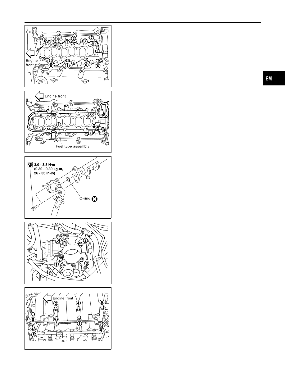
TIGHTENING PROCEDURES

NHEM0006S01

Intake Manifold

NHEM0006S0101

I

Tighten in numerical order shown in the figure.

1.

Tighten all bolts and nuts to 5 to 10 N·m (0.5 to 1.0 kg-m, 44
to 86 in-lb).

2.

Finally tighten all bolts and nuts to 26 to 31 N·m (2.7 to 3.2
kg-m, 20 to 23 ft-lb).

I

Tighten all bolts and nuts to the final torque, evenly dividing the
tightening into at least five steps.

SEM951F

Fuel Tube

NHEM0006S0102

I

Tighten in numerical order shown in the figure.

1.

Tighten all bolts to 9.3 to 10.8 N·m (0.95 to 1.1 kg-m, 79 to 95
in-lb).

2.

Then tighten all bolts to 21 to 26 N·m (2.1 to 2.7 kg-m, 15 to
20 ft-lb).

SEM952F

Fuel Pressure Regulator

NHEM0006S0103

Tighten fuel pressure regulator to 2.9 to 3.8 N·m (0.3 to 0.39 kg-m,
26.0 to 33.9 in-lb).

I

Tighten screws evenly several times to have the fuel pres-
sure regulator tightened at the specified torque.

I

Always replace O-ring with new ones.

I

Lubricate O-ring with new engine oil.

SEM587G

Throttle Body

NHEM0006S0105

I

Tighten in numerical order shown in the figure.

1.

Tighten all bolts to 8.8 to 10.8 N·m (0.9 to 1.1 kg-m, 79 to 95
in-lb).

2.

Then tighten all bolts to 17.7 to 21.6 N·m (1.8 to 2.2 kg-m, 13
to 16 ft-lb).

SEM954F

Intake Manifold Collector

NHEM0006S0107

Tighten bolts and nuts to 11 to 15 N·m (1.1 to 1.6 kg-m, 8 to 11 ft-lb)
in numerical order shown in the figure.

GI

MA

LC

EC

FE

AT

AX

SU

BR

ST

RS

BT

HA

SC

EL

IDX

OUTER COMPONENT PARTS

Removal and Installation (Cont’d)

EM-11

NHEM0007

SEM087G

1.

Warm up engine.

2.

Turn ignition switch OFF.

3.

Release fuel pressure.
Refer to EC-49, “Fuel Pressure Release”.

4.

Disconnect

ignition

coil

with

power

transistor

harness

connectors, then remove ignition coils.

5.

Remove all spark plugs.

6.

Remove fuse for fuel injector.

SEM909E

SEM387C

7.

Attach a compression tester to No. 1 cylinder.

8.

Depress accelerator pedal fully to keep throttle valve wide
open.

9.

Crank engine and record highest gauge indication.

10. Repeat the measurement on each cylinder as shown above.

I

Always use a fully-charged battery to obtain specified
engine speed.

Unit: kPa (kg/cm

2

, psi)/rpm

Standard

Minimum

Difference limit between

cylinders

1,275 (13.0, 185)/300

981 (10.0, 142)/300

98 (1.0, 14)/300

11. If compression in one or more cylinders is low:
a.

Pour a small amount of engine oil into cylinders through spark
plug holes.

b.

Retest compression.

I

If adding oil helps compression, piston rings may be worn
or damaged. If so, replace piston rings after checking pis-
ton.

I

If pressure stays low, a valve may be sticking or seating
improperly. Inspect and repair valve and valve seat. (Refer
to SDS, EM-73 
and EM-76.) If valve or valve seat is dam-
aged excessively, replace them.

I

If compression stays low in two cylinders that are next to
each other:

a)

The cylinder head gasket may be leaking, or

b)

Both cylinders may have valve component damage. Inspect
and repair as necessary.

MEASUREMENT OF COMPRESSION PRESSURE

EM-12

Components

NHEM0008

SEM574G

Removal

NHEM0009

CAUTION:

When removing the aluminum oil pan from engine, first
remove the crankshaft position sensors (POS and REF) from
the assembly.
Be careful not to damage sensor edges and signal plate teeth.
1.

Remove engine undercover.

2.

Drain engine oil.

SEM956F

3.

Remove steel oil pan bolts.

SEM957F

4.

Remove steel oil pan.

a.

Insert Tool between aluminum oil pan and steel oil pan.

I

Be careful not to damage aluminum mating surface.

I

Do not insert screwdriver, or oil pan flange will be
deformed.

GI

MA

LC

EC

FE

AT

AX

SU

BR

ST

RS

BT

HA

SC

EL

IDX

OIL PAN

Components

EM-13

SEM960F

b.

Slide Tool by tapping on the side of the Tool with a hammer.

c.

Remove steel oil pan.

SEM575G

5.

Remove oil strainer.

SEM834FA

6.

Remove front exhaust tube and its support.
Refer to FE-10, “Removal and Installation”.

SEM811E

7.

Set a suitable transmission jack under transaxle and hoist
engine with engine slinger.

8.

Remove crankshaft position sensors (POS and REF) from oil
pan.

9.

Remove front and rear engine mounting nuts and bolts.

10. Remove center member.

OIL PAN

Removal (Cont’d)

EM-14


Content   ..  471  472  473  474   ..