Infiniti I30 (A33). Manual - part 373
INSPECTION/THERMAL TRANSMITTER
=NHEL0046S09
1
CHECK THERMAL TRANSMITTER
Refer to “THERMAL TRANSMITTER CHECK” (EL-162).
OK or NG
OK
©
GO TO 2.
NG
©
Replace.
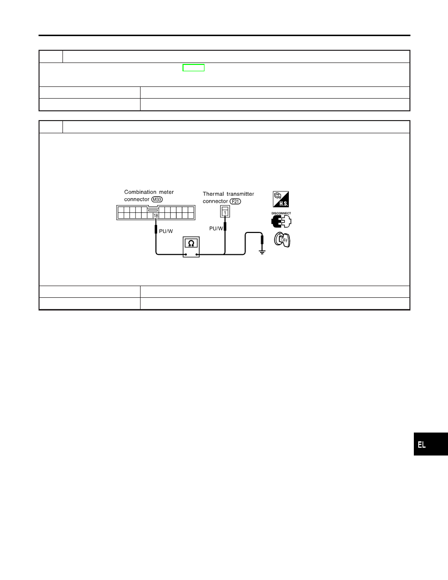
2
CHECK HARNESS FOR OPEN OR SHORT
1. Disconnect combination meter connector and thermal transmitter connector.
2. Check continuity between combination meter terminal 18 and thermal transmitter terminal 1.
Continuity should exist.
3. Check continuity between combination meter terminal 18 and ground.
Continuity should not exist.
SEL184W
OK or NG
OK
©
Thermal transmitter is OK.
NG
©
Repair harness or connector.
GI
MA
EM
LC
EC
FE
AT
AX
SU
BR
ST
RS
BT
HA
SC
IDX
METERS AND GAUGES
Trouble Diagnoses (Cont’d)
EL-161