Infiniti I30 (A33). Manual - part 269


  Index      Infiniti     Infiniti I30 (A33) - service repair manual 2001 year


Search            


Content   ..  267  268  269  270   ..


Infiniti I30 (A33). Manual - part 269


I

Rubber hose from EVAP canister vent control valve to water
separator

DTC Confirmation Procedure

NHEC0239

NOTE:
If “DTC Confirmation Procedure” has been previously conducted,
always turn ignition switch “OFF” and wait at least 10 seconds
before conducting the next test.
TESTING CONDITION:
Always perform test at a temperature of 5°C (41°F) or more.

SEF194Y

SEF340X

WITH CONSULT-II

NHEC0239S01

1)

Start engine and warm it up to normal operating temperature.

2)

Turn ignition switch “OFF” and wait at least 10 seconds.

3)

Turn ignition switch “ON”.

4)

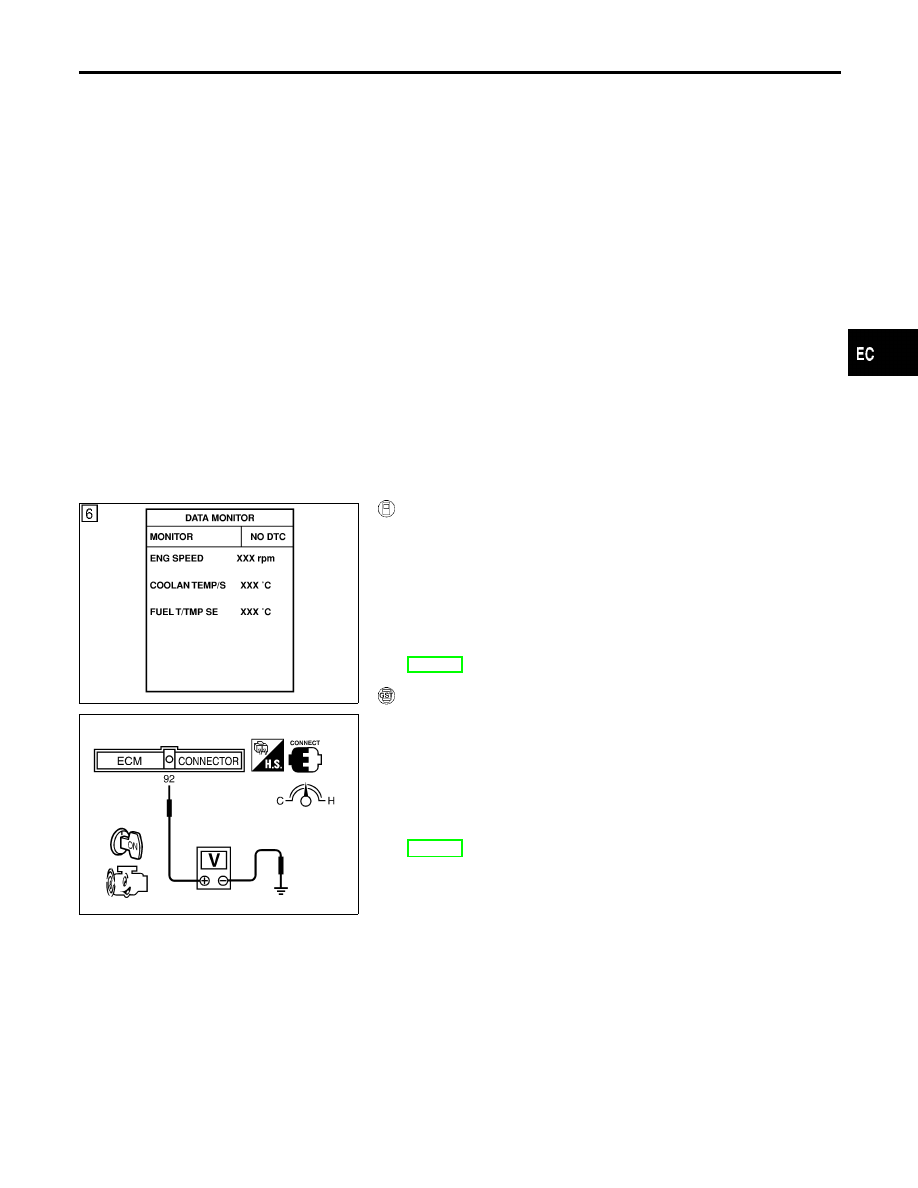
Select “DATA MONITOR” mode with CONSULT-II.

5)

Make sure that “FUEL T/TEMP SE” is more than 0°C (32°F).

6)

Start engine and wait at least 20 seconds.

7)

If 1st trip DTC is detected, go to “Diagnostic Procedure”,
EC-393.

WITH GST

NHEC0239S02

1)

Start engine and warm it up to normal operating temperature.

2)

Check that voltage between ECM terminal 92 (Fuel tank tem-
perature sensor signal) and ground is less than 4.2V.

3)

Turn ignition switch “OFF” and wait at least 10 seconds.

4)

Start engine and wait at least 20 seconds.

5)

Select “MODE 7” with GST.

6)

If 1st trip DTC is detected, go to “Diagnostic Procedure”,
EC-393.

GI

MA

EM

LC

FE

AT

AX

SU

BR

ST

RS

BT

HA

SC

EL

IDX

DTC P0450 EVAPORATIVE EMISSION (EVAP) CONTROL SYSTEM PRESSURE

SENSOR

Possible Cause (Cont’d)

EC-391

Wiring Diagram

NHEC0240

MEC360D

SEF623XB

DTC P0450 EVAPORATIVE EMISSION (EVAP) CONTROL SYSTEM PRESSURE

SENSOR

Wiring Diagram

EC-392

Diagnostic Procedure

NHEC0241

1

CHECK RUBBER TUBE

1. Turn ignition switch “OFF”.
2. Check rubber tube connected to the EVAP control system pressure sensor for clogging, vent, kink, disconnection or

improper connection.

SEF268X

OK or NG

OK

©

GO TO 2.

NG

©

Reconnect, repair or replace.

2

RETIGHTEN GROUND SCREWS

Loosen and retighten engine ground screws.

SEF255X

©

GO TO 3.

3

CHECK CONNECTOR

1. Disconnect EVAP control system pressure sensor harness connector.
2. Check sensor harness connector for water.

Water should not exist.

OK or NG

OK

©

GO TO 4.

NG

©

Repair or replace harness connector.

GI

MA

EM

LC

FE

AT

AX

SU

BR

ST

RS

BT

HA

SC

EL

IDX

DTC P0450 EVAPORATIVE EMISSION (EVAP) CONTROL SYSTEM PRESSURE

SENSOR

Diagnostic Procedure

EC-393

4

CHECK EVAP CONTROL SYSTEM PRESSURE SENSOR POWER SUPPLY CIRCUIT

1. Turn ignition switch “ON”.
2. Check voltage between EVAP control system pressure sensor terminal 1 and ground with CONSULT-II or tester.

SEF341X

OK or NG

OK

©

GO TO 6.

NG

©

GO TO 5.

5

DETECT MALFUNCTIONING PART

Check the following.

I

Harness connectors B2, M2

I

Harness connectors M81, F49

I

Harness for open or short between EVAP control system pressure sensor and ECM

©

Repair harness or connectors.

6

CHECK EVAP CONTROL SYSTEM PRESSURE SENSOR GROUND CIRCUIT FOR OPEN AND SHORT

1. Turn ignition switch “OFF”.
2. Check harness continuity between EVAP control system pressure sensor terminal 3 and engine ground.

Refer to Wiring Diagram.

Continuity should exist.

3. Also check harness for short to power.

OK or NG

OK

©

GO TO 8.

NG

©

GO TO 7.

7

DETECT MALFUNCTIONING PART

Check the following.

I

Harness connectors B2, M2

I

Harness connectors M81, F49

I

Harness for open or short between EVAP control system pressure sensor and ECM

I

Harness for open or short between EVAP control system pressure sensor and TCM (Transmission Control Module)

©

Repair open circuit or short to power in harness or connectors.

DTC P0450 EVAPORATIVE EMISSION (EVAP) CONTROL SYSTEM PRESSURE

SENSOR

Diagnostic Procedure (Cont’d)

EC-394


Content   ..  267  268  269  270   ..