Infiniti I30 (A33). Manual - part 237
4
CHECK HO2S2 (REAR) GROUND CIRCUIT FOR OPEN AND SHORT
1. Check harness continuity between HO2S2 (rear) terminal 4 and engine ground.
Refer to Wiring Diagram.
Continuity should exist.
2. Also check harness for short to power.
OK or NG
OK (With CONSULT-II)
©
GO TO 5.
OK (Without CONSULT-
II)
©
GO TO 6.
NG
©
Repair open circuit or short to power in harness or connectors.
5
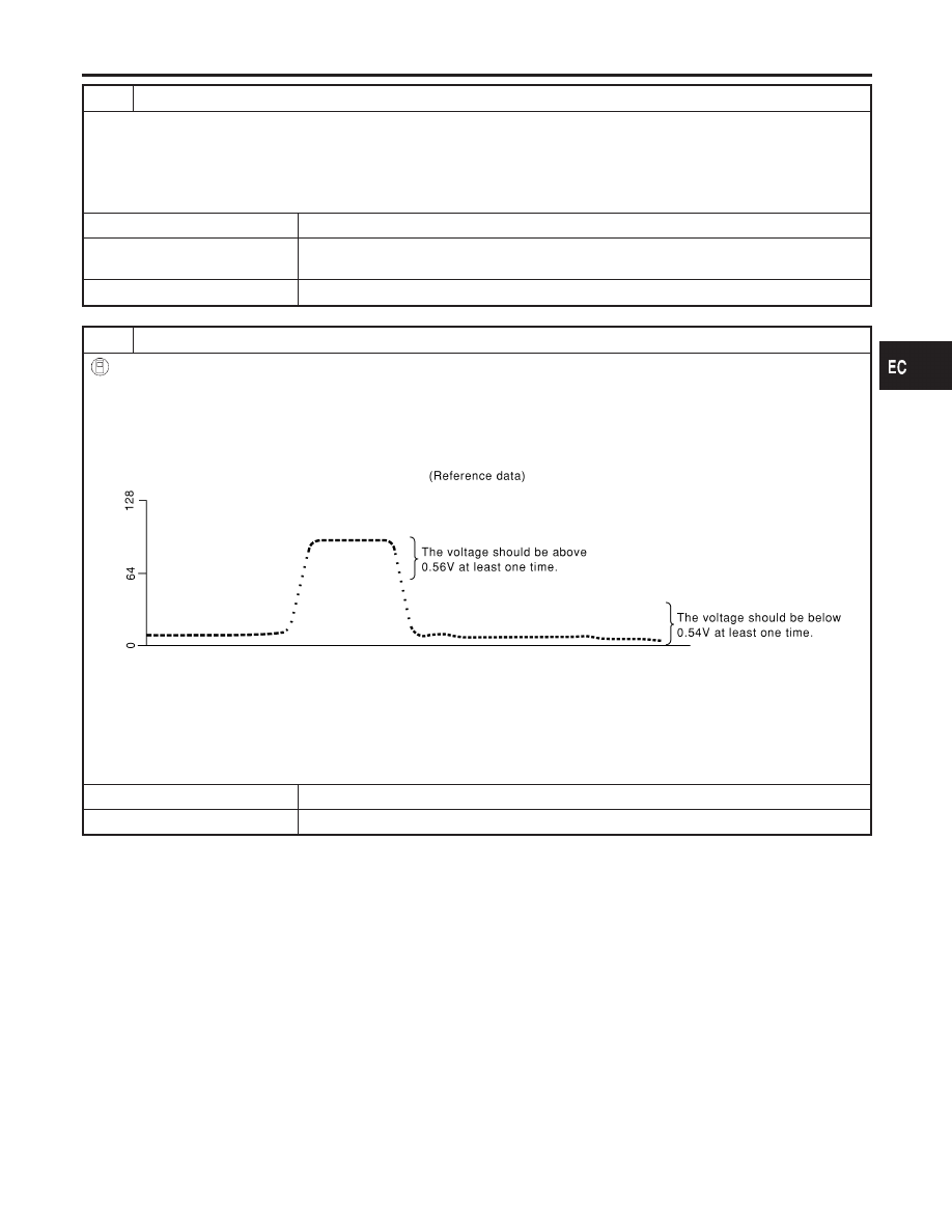
CHECK HEATED OXYGEN SENSOR 2 (REAR)
With CONSULT-II
1. Start engine and drive vehicle at a speed of more than 70 km/h (43 MPH) for 2 consecutive minutes.
2. Stop vehicle with engine running.
3. Select “FUEL INJECTION” in “ACTIVE TEST” mode, and select “HO2S2 (B1)/(B2)” as the monitor item with CONSULT-
II.
4. Check “HO2S2 (B1)/(B2)” at idle speed when adjusting “FUEL INJECTION” to
±
25%.
SEF066Y
“HO2S2 (B1)/(B2)” should be above 0.56V at least once when the “FUEL INJECTION” is +25%.
“HO2S2 (B1)/(B2)” should be below 0.54V at least once when the “FUEL INJECTION” is −25%.
CAUTION:
Discard any heated oxygen sensor which has been dropped from a height of more than 0.5 m (19.7 in) onto a
hard surface such as a concrete floor; use a new one.
OK or NG
OK
©
GO TO 9.
NG
©
GO TO 8.
GI
MA
EM
LC
FE
AT
AX
SU
BR
ST
RS
BT
HA
SC
EL
IDX
DTC P0138 (BANK 1), P0158 (BANK 2) HO2S2 (REAR) (MAX. VOLTAGE
MONITORING)
Diagnostic Procedure (Cont’d)
EC-263