Infiniti I30 (A33). Manual - part 212


  Index      Infiniti     Infiniti I30 (A33) - service repair manual 2001 year


Search            


Content   ..  210  211  212  213   ..


Infiniti I30 (A33). Manual - part 212


Diagnostic Procedure

NHEC0063

1

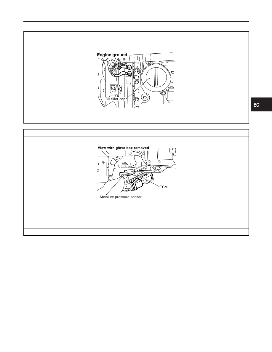
RETIGHTEN GROUND SCREWS

1. Turn ignition switch “OFF”.
2. Loosen and retighten engine ground screws.

SEF255X

©

GO TO 2.

2

CHECK ABSOLUTE PRESSURE SENSOR CONNECTOR FOR WATER

1. Disconnect absolute pressure sensor harness connector.

SEC004C

2. Check sensor harness connector for water.

Water should not exist.

OK or NG

OK

©

GO TO 3.

NG

©

Repair or replace harness connector.

GI

MA

EM

LC

FE

AT

AX

SU

BR

ST

RS

BT

HA

SC

EL

IDX

DTC P0105 ABSOLUTE PRESSURE SENSOR

Diagnostic Procedure

EC-163

3

CHECK ABSOLUTE PRESSURE SENSOR POWER SUPPLY CIRCUIT

1. Turn ignition switch “ON”.
2. Check voltage between absolute pressure sensor terminal 1 and ground with CONSULT-II or tester.

SEF299X

OK or NG

OK

©

GO TO 4.

NG

©

Repair harness or connectors.

4

CHECK ABSOLUTE PRESSURE SENSOR GROUND CIRCUIT FOR OPEN AND SHORT

1. Turn ignition switch “OFF”.
2. Check harness continuity between absolute pressure sensor terminal 3 and engine ground.

Refer to Wiring Diagram.

Continuity should exist.

3. Also check harness for short to power.

OK or NG

OK

©

GO TO 6.

NG

©

GO TO 5.

5

DETECT MALFUNCTIONING PART

Check the following.

I

Harness for open or short between ECM and absolute pressure sensor

I

Harness for open or short between TCM (Transmission Control Module) and absolute pressure sensor

©

Repair open circuit or short to power in harness or connectors.

6

CHECK ABSOLUTE PRESSURE SENSOR INPUT SIGNAL CIRCUIT FOR OPEN AND SHORT

1. Disconnect ECM harness connector.
2. Check harness continuity between ECM terminal 80 and absolute pressure sensor terminal 2.

Continuity should exist.

3. Also check harness for short to ground and short to power.

OK or NG

OK

©

GO TO 7.

NG

©

Repair open circuit or short to ground or short to power in harness or connectors.

DTC P0105 ABSOLUTE PRESSURE SENSOR

Diagnostic Procedure (Cont’d)

EC-164

7

CHECK ABSOLUTE PRESSURE SENSOR

1. Remove absolute pressure sensor with its harness connector connected.
2. Remove hose from absolute pressure sensor.
3. Install a vacuum pump to absolute pressure sensor.
4. Turn ignition switch “ON” and check output voltage between ECM terminal 80 and engine ground under the following

conditions.

SEF300X

CAUTION:

I

Always calibrate the vacuum pump gauge when using it.

I

Do not apply below −93.3 kPa (–700 mmHg, –27.56 inHg) or over 101.3 kPa (760 mmHg, 29.92 inHg) of pressure.

OK or NG

OK

©

GO TO 8.

NG

©

Replace absolute pressure sensor.

8

CHECK ABSOLUTE PRESSURE SENSOR SHIELD CIRCUIT FOR OPEN AND SHORT

1. Turn ignition switch “OFF”.
2. Disconnect joint connector-18.
3. Check the following.

I

Continuity between joint connector terminal 2 and ground
Refer to Wiring Diagram.

I

Joint connector
(Refer to EL-525, “HARNESS LAYOUT”.)

Continuity should exist.

4. Also check harness for short to power.
5. Then reconnect joint connector-18.

OK or NG

OK

©

GO TO 9.

NG

©

Repair open circuit or short to power in harness or connectors.

9

CHECK INTERMITTENT INCIDENT

Refer to “TROUBLE DIAGNOSIS FOR INTERMITTENT INCIDENT”, EC-144.

©

INSPECTION END

GI

MA

EM

LC

FE

AT

AX

SU

BR

ST

RS

BT

HA

SC

EL

IDX

DTC P0105 ABSOLUTE PRESSURE SENSOR

Diagnostic Procedure (Cont’d)

EC-165

SEF258X

SEF012P

Component Description

NHEC0064

The intake air temperature sensor is mounted to the air duct hous-
ing. The sensor detects intake air temperature and transmits a sig-
nal to the ECM.
The temperature sensing unit uses a thermistor which is sensitive
to the change in temperature. Electrical resistance of the thermistor
decreases in response to the temperature rise.
<Reference data>

Intake air

temperature

°C (°F)

Voltage*

V

Resistance

k

20 (68)

3.5

2.1 - 2.9

80 (176)

1.23

0.27 - 0.38

*: These data are reference values and are measured between ECM terminal 64
(Intake air temperature sensor) and body ground.

CAUTION:

Do not use ECM ground terminals when measuring input/
output voltage. Doing so may result in damage to the ECM’s
transistor. Use a ground other than ECM terminals, such as
the ground.

On Board Diagnosis Logic

NHEC0065

Malfunction is detected when
(Malfunction A) an excessively low or high voltage from the sen-
sor is sent to ECM,
(Malfunction B) rationally incorrect voltage from the sensor is sent
to ECM, compared with the voltage signal from engine coolant
temperature sensor.

Possible Cause

NHEC0428

I

Harness or connectors
(The sensor circuit is open or shorted.)

I

Intake air temperature sensor

DTC Confirmation Procedure

NHEC0066

Perform “PROCEDURE FOR MALFUNCTION A” first. If 1st trip
DTC cannot be confirmed, perform “PROCEDURE FOR MAL-
FUNCTION B”.
NOTE:
If “DTC Confirmation Procedure” has been previously conducted,
always turn ignition switch “OFF” and wait at least 10 seconds
before conducting the next test.

DTC P0110 INTAKE AIR TEMPERATURE SENSOR

Component Description

EC-166


Content   ..  210  211  212  213   ..