Infiniti I30 (A33). Manual - part 139


  Index      Infiniti     Infiniti I30 (A33) - service repair manual 2001 year


Search            


Content   ..  137  138  139  140   ..


Infiniti I30 (A33). Manual - part 139


5. Pedal Vibration and Noise

=NHBR0069

1

INSPECTION START

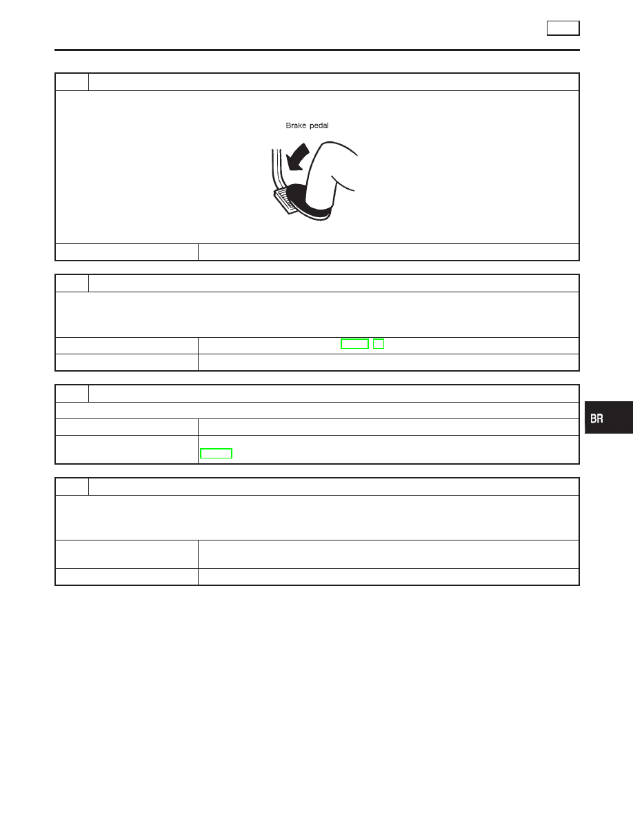
Pedal vibration and noise inspection

SAT797A

©

GO TO 2.

2

CHECK SYMPTOM

1. Apply brake.
2. Start engine.

Does the symptom appear only when engine is started?

Yes

©

Carry out self-diagnosis. Refer to BR-91, 94.

No

©

GO TO 3.

3

RECHECK SYMPTOM

Does the symptom appear when electrical equipment switches (such as headlamp) are operated?

Yes

©

GO TO 4.

No

©

Go to “3. CHECK WARNING LAMP INDICATION” in “2. Unexpected Pedal Action”,
BR-136.

4

CHECK WHEEL SENSOR

Check wheel sensor shield ground. For location of shield ground, refer to wiring diagram and “HARNESS LAYOUT” in EL
section.

Is wheel sensor shield grounded properly?

Yes

©

Check control unit pin terminals for damage or the connection of control unit harness
connector. Reconnect control unit harness connector. Then retest.

No

©

Repair.

NOTE:
ABS may operate and cause vibration under any of the following
conditions.

I

Applying brake gradually when shifting or operating clutch.

I

Low friction (slippery) road.

I

High speed cornering.

I

Driving over bumps and pot holes.

I

Engine speed is over 5,000 rpm with vehicle stopped.

GI

MA

EM

LC

EC

FE

AT

AX

SU

ST

RS

BT

HA

SC

EL

IDX

TROUBLE DIAGNOSES FOR SYMPTOMS

TCS

5. Pedal Vibration and Noise

BR-139

6. ABS Warning Lamp Does Not Come On
When Ignition Switch Is Turned On

=NHBR0074

1

INSPECTION START

Warning lamp circuit inspection

SBR334EB

©

GO TO 2.

2

CHECK FUSE

Check 10A fuse No. 30 for warning lamp. For fuse layout, refer to “POWER SUPPLY ROUTING” in EL section.

Is fuse OK?

Yes

©

GO TO 3.

No

©

Replace fuse.

TROUBLE DIAGNOSES FOR SYMPTOMS

TCS

6. ABS Warning Lamp Does Not Come On When Ignition Switch Is Turned On

BR-140

3

CHECK ABS CONTROL UNIT POWER SUPPLY CIRCUIT

1. Install 10A fuse.
2. Remove solenoid valve relay.
3. Disconnect connectors from control unit and actuator.
4. Check voltage between control unit connector terminal 30 and ground after turning ignition switch “ON”.

SBR715DD

Does battery voltage exist after turning ignition switch “ON”?

Yes

©

GO TO 5.

No

©

GO TO 4.

4

CHECK WARNING LAMP

Check warning lamp bulb.

Is warning lamp bulb OK?

Yes

©

Repair harness and connectors between fuse and control unit connector terminal 30
(including combination meter).

No

©

Replace bulb.

GI

MA

EM

LC

EC

FE

AT

AX

SU

ST

RS

BT

HA

SC

EL

IDX

TROUBLE DIAGNOSES FOR SYMPTOMS

TCS

6. ABS Warning Lamp Does Not Come On When Ignition Switch Is Turned On (Cont’d)

BR-141

5

CHECK CIRCUIT

1. Remove solenoid valve relay.
2. Check continuity between control unit terminals and solenoid valve relay terminals.

MTBL0091

NOTE:
Pay attention to tester polarity.
Specifications may vary depending on the type of tester.
Before performing this inspection, refer to the instruction manual of the tester.

SBR105EF

Does continuity exist?

Yes

©

GO TO 6.

No

©

Check the following.

I

Harness connectors E33, E91

I

Harness for open or short between solenoid valve relay terminal (relay box side) and
control unit

6

CHECK SOLENOID VALVE RELAY

Refer to “8. CHECK SOLENOID VALVE RELAY”, “Solenoid Valve Relay”, BR-114.

Is solenoid valve relay OK?

Yes

©

Go to “Low Voltage”, BR-126.

No

©

Replace solenoid valve relay.

TROUBLE DIAGNOSES FOR SYMPTOMS

TCS

6. ABS Warning Lamp Does Not Come On When Ignition Switch Is Turned On (Cont’d)

BR-142


Content   ..  137  138  139  140   ..