Infiniti I30 (A33). Manual - part 133


  Index      Infiniti     Infiniti I30 (A33) - service repair manual 2001 year


Search            


Content   ..  131  132  133  134   ..


Infiniti I30 (A33). Manual - part 133


5

CHECK GROUND CIRCUIT

Refer to CONTROL UNIT GROUND and ACTUATOR MOTOR GROUND in Ground Circuit Check, BR-104.

Is ground circuit OK?

Yes

©

GO TO 6.

No

©

Repair harness and connectors.
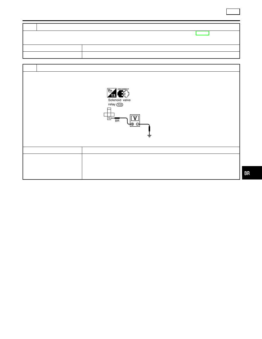
6

CHECK SOLENOID VALVE POWER SUPPLY CIRCUIT

1. Remove solenoid valve relay.
2. Check voltage between solenoid valve relay terminal 5 and ground.

SBR777DI

Does battery voltage exist?

Yes

©

GO TO 7.

No

©

Check the following.

I

Harness connector E33

I

Harness for open or short between solenoid valve terminal (relay box side) and fusible
link
If NG, repair harness or connectors.

GI

MA

EM

LC

EC

FE

AT

AX

SU

ST

RS

BT

HA

SC

EL

IDX

TROUBLE DIAGNOSES FOR SELF-DIAGNOSTIC ITEMS

TCS

Solenoid Valve Relay (Cont’d)

BR-115

7

CHECK CIRCUIT

1. Disconnect control unit connector.
2. Check continuity between control unit connector terminals and solenoid valve relay terminals.

MTBL0089

SBR778DH

Does continuity exist?

Yes

©

GO TO 8.

No

©

Check the following.

I

Harness connector E91

I

Harness for open or short between solenoid valve relay terminal (relay box side) and
control unit
If NG, repair harness or connectors.

TROUBLE DIAGNOSES FOR SELF-DIAGNOSTIC ITEMS

TCS

Solenoid Valve Relay (Cont’d)

BR-116

8

CHECK SOLENOID VALVE RELAY

MTBL0090

While applying battery voltage to relay terminals, insert fuse into the circuit.

SBR776D

Is solenoid valve relay OK?

Yes

©

Go to “ABS Actuator Solenoid Valve”, BR-110.

No

©

Replace solenoid valve relay.

9

REPLACE FUSIBLE LINK

Replace fusible link.

Does the fusible link blow out when ignition switch is turned “ON”?

Yes

©

GO TO 10.

No

©

INSPECTION END

GI

MA

EM

LC

EC

FE

AT

AX

SU

ST

RS

BT

HA

SC

EL

IDX

TROUBLE DIAGNOSES FOR SELF-DIAGNOSTIC ITEMS

TCS

Solenoid Valve Relay (Cont’d)

BR-117

10

CHECK RELAY UNIT POWER SUPPLY CIRCUIT

1. Remove solenoid valve relay.
2. Check continuity between solenoid valve relay terminal 5 and ground.

SBR779DI

Does continuity exist?

Yes

©

GO TO 11.

No

©

Check the following.

I

Harness connector E33

I

Harness for open or short between solenoid valve terminal (relay box side) and fusible
link
If NG, repair harness or connectors.

11

CHECK ABS SOLENOID VALVE RELAY

1. Disconnect ABS actuator 2-pin connectors and control unit connector.
2. Check continuity between ABS actuator 2-pin connector E5 (body side) terminal 19 and ground.

SBR493DH

Does continuity exist?

Yes

©

Replace ABS relay box.

No

©

GO TO 12.

TROUBLE DIAGNOSES FOR SELF-DIAGNOSTIC ITEMS

TCS

Solenoid Valve Relay (Cont’d)

BR-118


Content   ..  131  132  133  134   ..