Infiniti I30 (A33). Manual - part 125
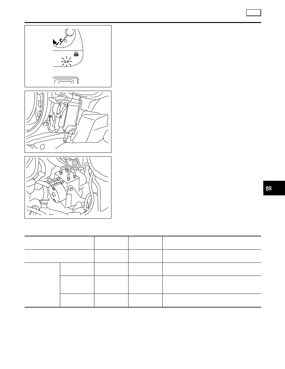
SBR655E
SBR530E
CONTROL UNIT
NHBR0052S02
ABS Function
NHBR0052S0201
The control unit computes the wheel rotating speed by the signal
current sent from the sensor. Then it supplies a DC current to the
actuator solenoid valve. It also controls ON-OFF operation of the
valve relay and motor relay. If any electrical malfunction should be
detected in the system, the warning lamp is turned on. In this
condition, the ABS will be deactivated, and the vehicle’s brake
system reverts to normal operation.
TCS Function
NHBR0052S0202
Drive wheel slippage is detected by the 4-wheel rotating speed
signal. When the wheel slip becomes excessive, the TCS operates,
causing the SLIP indicator lamp to flash. And, at the same time, a
fuel-cut signal to be sent to the ECM and a signal requiring a
change in the shift schedule is sent to the TCM. When the TCS
OFF switch is used to cancel TCS function, the TCS OFF indica-
tor lamp will light. (TCS does not activate.) In case of a malfunc-
tion in the TCS, both the SLIP indicator lamp and the TCS OFF
indicator lamp will light, while shutting down the TCS system opera-
tion. The vehicle will operate in the same way as a vehicle not
equipped with the TCS.
SBR531E
ACTUATOR
NHBR0052S03
The actuator contains:
I
An electric motor and pump
I
Two relays
I
Eight solenoid valves, each inlet and outlet for
— LH front
— RH front
— LH rear
— RH rear
These components control the hydraulic circuit. The ABS control
unit directs the actuator to increase, hold or decrease hydraulic
pressure to all or individual wheels.
ABS Actuator Operation
NHBR0052S0301
Inlet solenoid
valve
Outlet solenoid
valve
Normal brake operation
OFF (Open)
OFF (Closed)
Master cylinder brake fluid pressure is directly trans-
mitted to caliper via the inlet solenoid valve.
ABS operation
Pressure hold
ON (Closed)
OFF (Closed)
Hydraulic circuit is shut off to hold the caliper brake
fluid pressure.
Pressure
decrease
ON (Closed)
ON (Open)
Caliper brake fluid is sent to reservoir via the outlet
solenoid valve. Then it is pushed up to the master
cylinder by pump.
Pressure
increase
OFF (Open)
OFF (Closed)
Master cylinder brake fluid pressure is transmitted to
caliper.
GI
MA
EM
LC
EC
FE
AT
AX
SU
ST
RS
BT
HA
SC
EL
IDX
DESCRIPTION
TCS
System Description (Cont’d)
BR-83