Infiniti I30 (A33). Manual - part 82
SAT550G
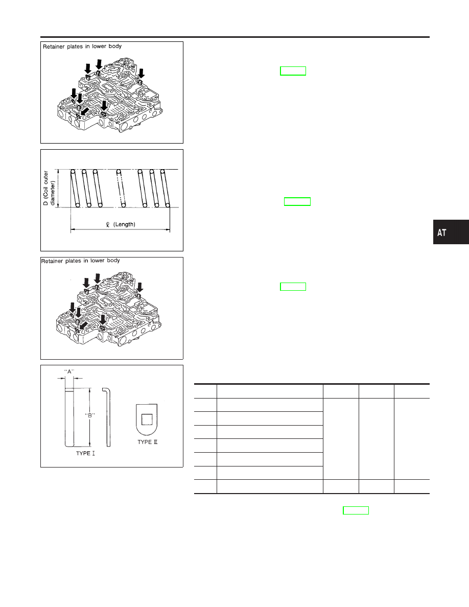
DISASSEMBLY
NHAT0142
I
Remove valves at retainer plate.
For removal procedures, refer to “DISASSEMBLY”, “Control
Valve Upper Body”, AT-321.
SAT138D
INSPECTION
NHAT0143
Valve Springs
NHAT0143S01
I
Check each valve spring for damage or deformation. Also
measure free length and outer diameter.
Inspection standard:
Refer to SDS, AT-383.
I
Replace valve springs if deformed or fatigued.
Control Valves
NHAT0143S02
I
Check sliding surfaces of control valves, sleeves and plugs for
damage.
SAT550A
ASSEMBLY
NHAT0144
I
Install control valves.
For installation procedures, refer to “ASSEMBLY”, “Control
Valve Upper Body”, AT-322.
SAT089F
Retainer Plate (Lower body)
NHAT0144S01
Unit: mm (in)
No.
Name of control valve and plug
Width A
Length B
Type
19
Pressure regulator valve
6.0
(0.236)
28.0
(1.102)
I
27
Accumulator control valve
30
Shift valve A
23
Overrun clutch control valve
2
Pressure modifier valve
35
Shuttle valve
9
Shift valve B
—
—
II
I
Install proper retainer plates.
Refer to “Control Valve Lower Body”, AT-324.
GI
MA
EM
LC
EC
FE
AX
SU
BR
ST
RS
BT
HA
SC
EL
IDX
REPAIR FOR COMPONENT PARTS
Control Valve Lower Body (Cont’d)
AT-325