Infiniti I30 (A33). Manual - part 47
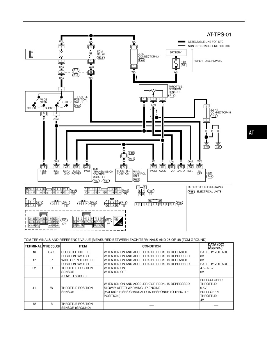
Wiring Diagram — AT — TPS
NHAT0074
MAT973A
SAT310K
GI
MA
EM
LC
EC
FE
AX
SU
BR
ST
RS
BT
HA
SC
EL
IDX
DTC P1705 THROTTLE POSITION SENSOR
Wiring Diagram — AT — TPS
AT-185
|
|
|
Wiring Diagram — AT — TPS NHAT0074 MAT973A SAT310K GI MA EM LC EC FE AX SU BR ST RS BT HA SC EL IDX DTC P1705 THROTTLE POSITION SENSOR Wiring Diagram — AT — TPS AT-185 |