Infiniti I30 (A33). Manual - part 31
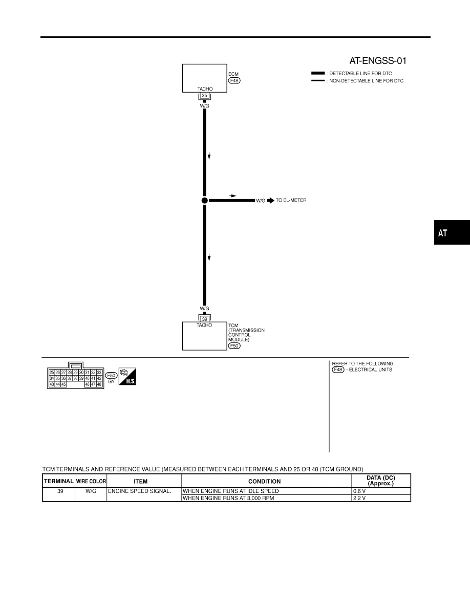
Wiring Diagram — AT — ENGSS
NHAT0044
MAT807A
SAT296K
GI
MA
EM
LC
EC
FE
AX
SU
BR
ST
RS
BT
HA
SC
EL
IDX
DTC P0725 ENGINE SPEED SIGNAL
Wiring Diagram — AT — ENGSS
AT-121
|
|
|
Wiring Diagram — AT — ENGSS NHAT0044 MAT807A SAT296K GI MA EM LC EC FE AX SU BR ST RS BT HA SC EL IDX DTC P0725 ENGINE SPEED SIGNAL Wiring Diagram — AT — ENGSS AT-121 |