Infiniti I30 (A33). Manual - part 27


  Index      Infiniti     Infiniti I30 (A33) - service repair manual 2001 year


Search            


Content   ..  25  26  27  28   ..


Infiniti I30 (A33). Manual - part 27


Diagnostic Procedure

NHAT0036

1

INSPECTION START

Do you have CONSULT-II?

Yes or No

Yes

©

GO TO 2.

No

©

GO TO 6.

2

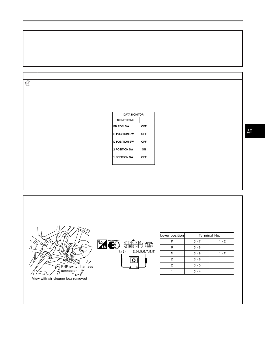
CHECK PARK/NEUTRAL POSITION (PNP) SWITCH CIRCUIT (With CONSULT-II)

With CONSULT-II

1. Turn ignition switch to ON position.

(Do not start engine.)

2. Select “TCM INPUT SIGNALS” in “DATA MONITOR” mode for “A/T” with CONSULT-II.
3. Read out P, R, N, D, 2 and 1 position switches moving selector lever to each position.

Check the signal of the selector lever position is indicated properly.

SAT701J

OK or NG

OK

©

GO TO 7.

NG

©

GO TO 3.

3

DETECT MALFUNCTIONING ITEM

Check the following item:

I

Park/neutral position (PNP) switch
Check continuity between terminals 1 and 2 and between terminals 3 and 4, 5, 6, 7, 8, 9 while moving manual shaft
through each position.

SAT615J

OK or NG

OK

©

GO TO 5.

NG

©

GO TO 4.

GI

MA

EM

LC

EC

FE

AX

SU

BR

ST

RS

BT

HA

SC

EL

IDX

DTC P0705 PARK/NEUTRAL POSITION SWITCH

Diagnostic Procedure

AT-105

4

CHECK MANUAL CONTROL CABLE ADJUSTMENT

Check PNP switch again with manual control cable disconnected from manual shaft of A/T assembly. Refer to test group
1.

OK or NG

OK

©

Adjust manual control cable. Refer to AT-282.

NG

©

Repair or replace PNP switch.

5

DETECT MALFUNCTIONING ITEM

Check the following items:

I

Harness for short or open between ignition switch and park/neutral position (PNP) switch (Main harness)

I

Harness for short or open between park/neutral position (PNP) switch and TCM (Main harness)

I

Fuse

I

Joint connector-3 M29

I

Ignition switch
Refer to EC-16, “POWER SUPPLY ROUTING”.

OK or NG

OK

©

GO TO 7.

NG

©

Repair or replace damaged parts.

6

CHECK PARK/NEUTRAL POSITION (PNP) SWITCH CIRCUIT (Without CONSULT-II)

Without CONSULT-II

1. Turn ignition switch to ON position. (Do not start engine.)
2. Check voltage between TCM terminals 26, 27, 34, 35, 36 and ground while moving selector lever through each posi-

tion.

SAT840J

OK or NG

OK

©

GO TO 7.

NG

©

GO TO 5.

7

CHECK DTC

Perform Diagnostic Trouble Code (DTC) confirmation procedure, AT-103.

OK or NG

OK

©

INSPECTION END

NG

©

GO TO 8.

DTC P0705 PARK/NEUTRAL POSITION SWITCH

Diagnostic Procedure (Cont’d)

AT-106

8

CHECK TCM INSPECTION

1. Perform TCM input/output signal inspection.
2. If NG, recheck TCM pin terminals for damage or loose connection with harness connector.

OK or NG

OK

©

INSPECTION END

NG

©

Repair or replace damaged parts.

GI

MA

EM

LC

EC

FE

AX

SU

BR

ST

RS

BT

HA

SC

EL

IDX

DTC P0705 PARK/NEUTRAL POSITION SWITCH

Diagnostic Procedure (Cont’d)

AT-107

SAT283HB

SAT021J

Description

NHAT0037

The A/T fluid temperature sensor detects the A/T fluid temperature
and sends a signal to the TCM.

CONSULT-II REFERENCE VALUE IN DATA MONITOR
MODE

NHAT0037S01

Remarks: Specification data are reference values.

Monitor item

Condition

Specification (Approximately)

A/T fluid temperature
sensor

Cold [20°C (68°F)]

"

Hot [80°C (176°F)]

1.5V

"

0.5V

2.5 k

"

0.3 k

TCM TERMINALS AND REFERENCE VALUE

NHAT0037S02

Remarks: Specification data are reference values.

Terminal

No.

Wire color

Item

Condition

Judgement

standard

(Approx.)

42

B

Throttle position
sensor
(Ground)

47

G

A/T fluid
temperature
sensor

When ATF temperature is 20°C (68°F).

1.5V

When ATF temperature is 80°C (176°F).

0.5V

On Board Diagnosis Logic

NHAT0204

Diagnostic trouble code ATF TEMP SEN/CIRC with CONSULT-II or
P0710 without CONSULT-II is detected when TCM receives an
excessively low or high voltage from the sensor.

DTC P0710 A/T FLUID TEMPERATURE SENSOR CIRCUIT

Description

AT-108


Content   ..  25  26  27  28   ..