Infiniti G37 Coupe. Manual - part 922


  Index      Infiniti     Infiniti G37 Coupe - service repair manual 2008 year


Search            


Content   ..  920  921  922  923   ..


Infiniti G37 Coupe. Manual - part 922


MWI-34

< FUNCTION DIAGNOSIS >

CLOCK

CLOCK

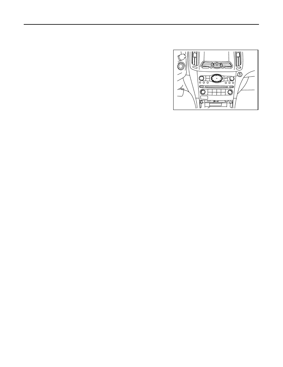
Component Parts Location

INFOID:0000000001606645

1

:  Clock

JSNIA0038GB

MWI

DIAGNOSIS SYSTEM (METER)

MWI-35

< FUNCTION DIAGNOSIS >

C

D

E

F

G

H

I

J

K

L

M

B

A

O

P

DIAGNOSIS SYSTEM (METER)

Diagnosis Description

INFOID:0000000001606646

SELF-DIAGNOSIS MODE

• Information display LCD segment operation can be checked in self-diagnosis mode.
• Meters/gauges can be checked in self-diagnosis mode.

OPERATION PROCEDURE

1.

Turn ignition switch ON, and switch the trip meter to “trip A” or “trip B”.
NOTE:
If the diagnosis function is activated with “trip A” displayed, the mileage on “trip A” is reset to “0000.0”.
(The same way for “trip B”.)

2.

Turn ignition switch OFF.

3.

While pressing the trip A/B reset switch (1), turn ignition switch
ON again.

4.

Make sure that the trip meter displays “0000.0”.

5.

Press the trip A/B reset switch at least 3 times. (Within 7 sec-
onds after the ignition switch is turned ON.)

6.

The unified meter control unit is turned to self-diagnosis mode.
• Displays "888888" (1) and "8888.8" (2) in the information display LCD (3) for approximately 5 seconds

and then blinks the segment dots of the information display LCD alternately. 

• Water temperature gauge and fuel gauge return to zero, and at the same time.

NOTE:
• Check tirp A/B reset switch and combination meter power supply and ground circuit when self-diagnosis

mode of combination meter does not start. Replace combination meter if they are normal.

• If any of the segments is not displayed, replace combination meter.

JSNIA0019GB

JSNIA0616GB

MWI-36

< FUNCTION DIAGNOSIS >

DIAGNOSIS SYSTEM (METER)

7.

Each meter activates during pressing trip A/B reset switch.

NOTE:
If any of the meter and gages is not activated, replace combination meter.

JSNIA0021GB

MWI

DIAGNOSIS SYSTEM (UNIFIED METER AND A/C AMP.)

MWI-37

< FUNCTION DIAGNOSIS >

C

D

E

F

G

H

I

J

K

L

M

B

A

O

P

DIAGNOSIS SYSTEM (UNIFIED METER AND A/C AMP.)

CONSULT-III Function (METER/M&A)

INFOID:0000000001606647

CONSULT-III APPLICATION ITEMS

CONSULT-III can perform the following diagnosis modes with CAN communication with the unified meter and
A/C amp.

SELF DIAG RESULT

Refer to 

MWI-100, "DTC Index"

.

DATA MONITOR

Display Item List

X: Applicable

System

Diagnosis mode

Description

METER/M&A

Self Diagnostic Result

Unified meter and A/C amp. checks the conditions and displays memorized error.

Data Monitor

Displays unified meter and A/C amp. input/output data in real time.

Display item [Unit]

MAIN

SIGNALS

Description

SPEED METER
[km/h]

X

Value of vehicle speed signal received from ABS actuator and electric unit (control 
unit) with CAN communication line.
NOTE:
655.35 is displayed when the malfunction signal is received.

SPEED OUTPUT
[km/h]

X

Vehicle speed signal value transmitted to other units with CAN communication 
line.
NOTE:
655.35 is displayed when the malfunction signal is received.

ODO OUTPUT
[km]

Odometer signal value transmitted to other units with CAN communication line.

TACHO METER
[rpm]

X

Value of the engine speed signal received from ECM with CAN communication 
line.
NOTE:
8191.875 is displayed when the malfunction signal is received.

FUEL METER
[L]

X

Fuel level indicated on combination meter.

W TEMP METER
[

°

C] 

X

Value of engine coolant temperature signal received from ECM with CAN commu-
nication line. 
NOTE:
215 is displayed when the malfunction signal is input.

ABS W/L
[On/Off]

Status of ABS warning lamp judged from ABS warning lamp signal received from 
ABS actuator and electric unit (control unit) with CAN communication line.

VDC/TCS IND
[On/Off]

Status of VDC OFF indicator lamp judged from VDC OFF indicator lamp signal re-
ceived from ABS actuator and electric unit (control unit) with CAN communication 
line.

SLIP IND
[On/Off]

Status of SLIP indicator lamp judged from slip indicator lamp signal received from 
ABS actuator and electric unit (control unit) with CAN communication line.

BRAKE W/L
[On/Off]

Status of brake warning lamp judged from brake warning lamp signal received 
from ABS actuator and electric unit (control unit) with CAN communication line.
NOTE:
Displays “Off” if the brake warning lamp is illuminated when the valve check starts, 
the parking brake switch is turned ON or the brake fluid level switch is turned ON.

DOOR W/L
[On/Off]

Status of door warning judged from door switch signal received from BCM with 
CAN communication line.

TRUNK/GLAS-H
[On/Off]

Status of trunk warning judged from trunk switch signal received from BCM with 
CAN communication line.


Content   ..  920  921  922  923   ..