Infiniti G37 Coupe. Manual - part 723
 

  Index      Infiniti     Infiniti G37 Coupe - service repair manual 2008 year


Search            


Content   ..  721  722  723  724   ..


Infiniti G37 Coupe. Manual - part 723


HOW TO READ WIRING DIAGRAMS

GI-11

< HOW TO USE THIS MANUAL >

C

D

E

F

G

H

I

J

K

L

M

B

GI

N

O

P

Description

INFOID:0000000001679176

SWITCH POSITIONS 

Switches are shown in wiring diagrams as if the vehicle is in the “normal” condition.
A vehicle is in the “normal” condition when:

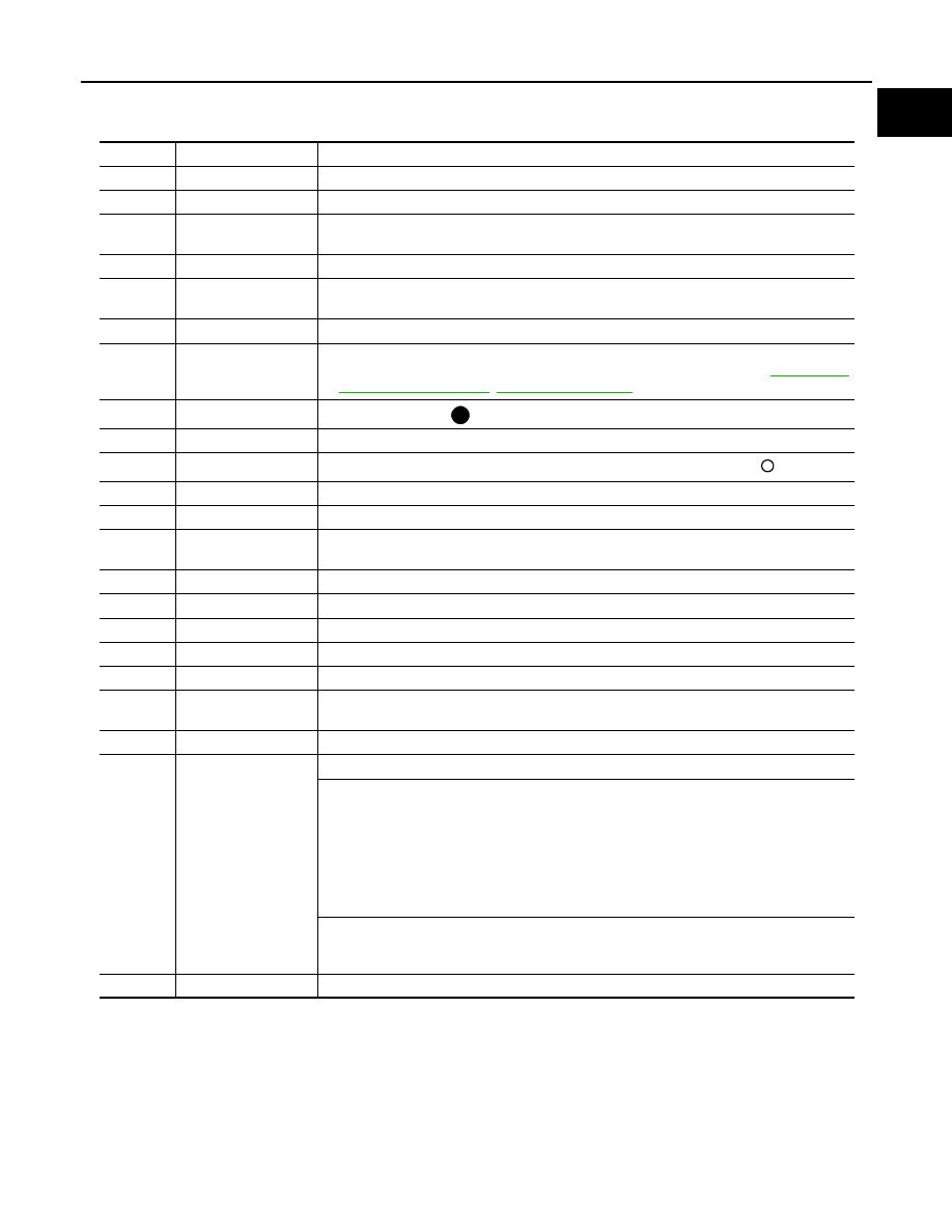
Number

Item

Description

1

Power supply

• This means the power supply of fusible link or fuse.

2

Fusible link

• “X” means the fusible link.

3

Number of fusible link/
fuse

• This means the number of fusible link or fuse location.

4

Fuse

• “/” means the fuse.

5

Current rating of fus-
ible link/fuse

• This means the current rating of the fusible link or fuse.

6

Optional splice

• The open circle shows that the splice is optional depending on vehicle application.

7

Connector number

• The letter shows which harness the connector is located in.
• Example “M”: main harness. For detail and to locate the connector, refer to 

PG-74, "How 

To Read Harness Layout"

, 

PG-76, "Main Harness"

.

8

Splice

• The shaded circle “

” means the splice.

9

Page crossing

• This circuit continues to an adjacent page.

10

Option abbreviation

• This means the vehicle specifications which layouts the circuit between “

”.

11

Relay

• This shows an internal representation of the relay.

12

Option description

• This shows a description of the option abbreviation used on the page.

13

Switch

• This shows that continuity exists between terminals 1 and 2 when the switch is in the A 

position. Continuity exists between terminals 1 and 3 when the switch is in the B position.

14

Circuit (Wiring)

• This means the wiring.

15

System branch

• This shows that the circuit is branched to other systems.

16

Shielded line

• The line enclosed by broken line circle shows shield wire.

17

Component name

• This shows the name of a component.

18

Ground (GND)

• This shows the ground connection.

19

Connector

• This means the connector information.
• This unit-side is described by the connector symbols.

20

Connectors

• This means that a transmission line bypasses two connectors or more.

21

Wire color

• This shows a code for the color of the wire.

B = Black
W = White
R = Red
G = Green
L = Blue
Y = Yellow
LG = Light Green

BR = Brown
OR or O = Orange
P = Pink
PU or V (Violet) = Purple
GY or GR = Gray
SB = Sky Blue
CH = Dark Brown
DG = Dark Green

• When the wire color is striped, the base color is given first, followed by the stripe color as 

shown below:
Example: L/W = Blue with White Stripe

22

Terminal number

• This means the terminal number of a connector.

GI-12

< HOW TO USE THIS MANUAL >

HOW TO READ WIRING DIAGRAMS

• ignition switch is “OFF”,
• doors, hood and trunk lid/back door are closed,
• pedals are not depressed, and
• parking brake is released.

MULTIPLE SWITCH

The continuity of multiple switch is described in two ways as shown below.
• The switch chart is used in schematic diagrams.
• The switch diagram is used in wiring diagrams.

SGI860

JSAIA0017GB

ABBREVIATIONS

GI-13

< HOW TO USE THIS MANUAL >

C

D

E

F

G

H

I

J

K

L

M

B

GI

N

O

P

ABBREVIATIONS

Abbreviation List

INFOID:0000000001679177

The following ABBREVIATIONS are used:

ABBREVIATION

DESCRIPTION

A/C

Air Conditioner

A/T

Automatic Transaxle/Transmission

ATF

Automatic Transmission Fluid

D

1

Drive range 1st gear

D

2

Drive range 2nd gear

D

3

Drive range 3rd gear

D

4

Drive range 4th gear

FR, RR

Front, Rear

LH, RH

Left-Hand, Right-Hand

M/T

Manual Transaxle/Transmission

OD

Overdrive

P/S

Power Steering

SAE

Society of Automotive Engineers, Inc.

SDS

Service Data and Specifications

SST

Special Service Tools

2WD

2-Wheel Drive

2

2

2nd range 2nd gear

2

1

2nd range 1st gear

1

2

1st range 2nd gear

1

1

1st range 1st gear

GI-14

< HOW TO USE THIS MANUAL >

TIGHTENING TORQUE OF STANDARD BOLTS

TIGHTENING TORQUE OF STANDARD BOLTS

Tightening Torque Table

INFOID:0000000001679178

*: Nominal diameter

1.

Special parts are excluded.

2.

This standard is applicable to bolts having the following marks embossed on the bolt head.

Grade

Bolt size

Bolt diam-

eter *

mm

Pitch

mm

Tightening torque (Without lubricant)

Hexagon head bolt

Hexagon flange bolt

N·m

kg-m

ft-lb

in-lb

N·m

kg-m

ft-lb

in-lb

4T

M6

6.0

1.0

5.5

0.56

4

49

7

0.71

5

62

M8

8.0

1.25

13.5

1.4

10

—

17

1.7

13

—

1.0

13.5

1.4

10

—

17

1.7

13

—

M10

10.0

1.5

28

2.9

21

—

35

3.6

26

—

1.25

28

2.9

21

—

35

3.6

26

—

M12

12.0

1.75

45

4.6

33

—

55

5.6

41

—

1.25

45

4.6

33

—

65

6.6

48

—

M14

14.0

1.5

80

8.2

59

—

100

10

74

—

7T

M6

6.0

1.0

9

0.92

7

80

11

1.1

8

97

M8

8.0

1.25

22

2.2

16

—

28

2.9

21

—

1.0

22

2.2

16

—

28

2.9

21

—

M10

10.0

1.5

45

4.6

33

—

55

5.6

41

—

1.25

45

4.6

33

—

55

5.6

41

—

M12

12.0

1.75

80

8.2

59

—

100

10

74

—

1.25

80

8.2

59

—

100

10

74

—

M14

14.0

1.5

130

13

96

—

170

17

125

—

9T

M6

6.0

1.0

11

1.1

8

—

13.5

1.4

10

—

M8 8.0

1.25

28

2.9

21

—

35

3.6

26

—

1.0

28

2.9

21

—

35

3.6

26

—

M10

10.0

1.5

55

5.6

41

—

80

8.2

59

—

1.25

55

5.6

41

—

80

8.2

59

—

M12

12.0

1.75

100

10

74

—

130

13

96

—

1.25

100

10

74

—

130

13

96

—

M14

14.0

1.5

170

17

125

—

210

21

155

—

MGI044A


Content   ..  721  722  723  724   ..