Infiniti G37 Coupe. Manual - part 657
EXL-48
< COMPONENT DIAGNOSIS >
[XENON TYPE]
B2514 HEIGHT SENSOR UNUSUAL [RR]
Is the measurement value within the standard value?
YES
>> Replace AFS control unit.
Less than the standard value >>GO TO 3.
Higher than the standard value>>GO TO 6.
3.
CHECK HEIGHT SENSOR POWER SUPPLY CIRCUIT OUTPUT VOLTAGE
1.
Turn the ignition switch OFF.
2.
Disconnect the height sensor connector.
3.
Turn the ignition switch ON.
4.
Check the voltage between the height sensor harness connector and the ground.
Is the measurement value within the standard value?
YES
>> GO TO 4.
NO
>> Repair the harnesses or connectors.
4.
CHECK HEIGHT SENSOR SIGNAL OPEN CIRCUIT
1.
Turn the ignition switch OFF.
2.
Disconnect AFS control unit connector.
3.
Check continuity between the AFS control unit harness connector and the height sensor harness connec-
tor.
Does continuity exist?
YES
>> GO TO 5.
NO
>> Repair the harnesses or connectors.
5.
CHECK HEIGHT SENSOR SIGNAL SHORT CIRCUIT
Check continuity between the height sensor harness connector and the ground.
Does continuity exist?
YES
>> Repair the harnesses or connectors.
NO
>> Replace the height sensor.
6.
CHECK HEIGHT SENSOR GROUND
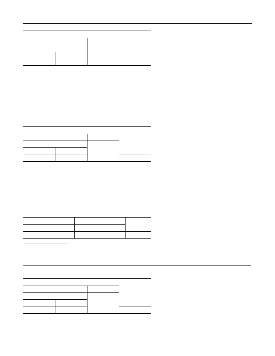
Terminals
Voltage
(Approx.)
(+)
(
−
)
AFS control unit
Ground
Connector
Terminal
M16
28
0.25 - 4.75 V
Terminals
Voltage
(Approx.)
(+)
(
−
)
Height sensor
Ground
Connector
Terminal
B32
1
4 - 6 V
AFS control unit
Height sensor
Continuity
Connector
Terminal
Connector
Terminal
M16
28
B32
2
Existed
Terminals
Continuity
(+)
(
−
)
Height sensor
Ground
Connector
Terminal
B32
2
Not existed