Infiniti G37 Coupe. Manual - part 625
OIL PAN (UPPER) AND OIL STRAINER
EM-75
< DISASSEMBLY AND ASSEMBLY >
C
D
E
F
G
H
I
J
K
L
M
A
EM
N
P
O
OIL PAN (UPPER) AND OIL STRAINER
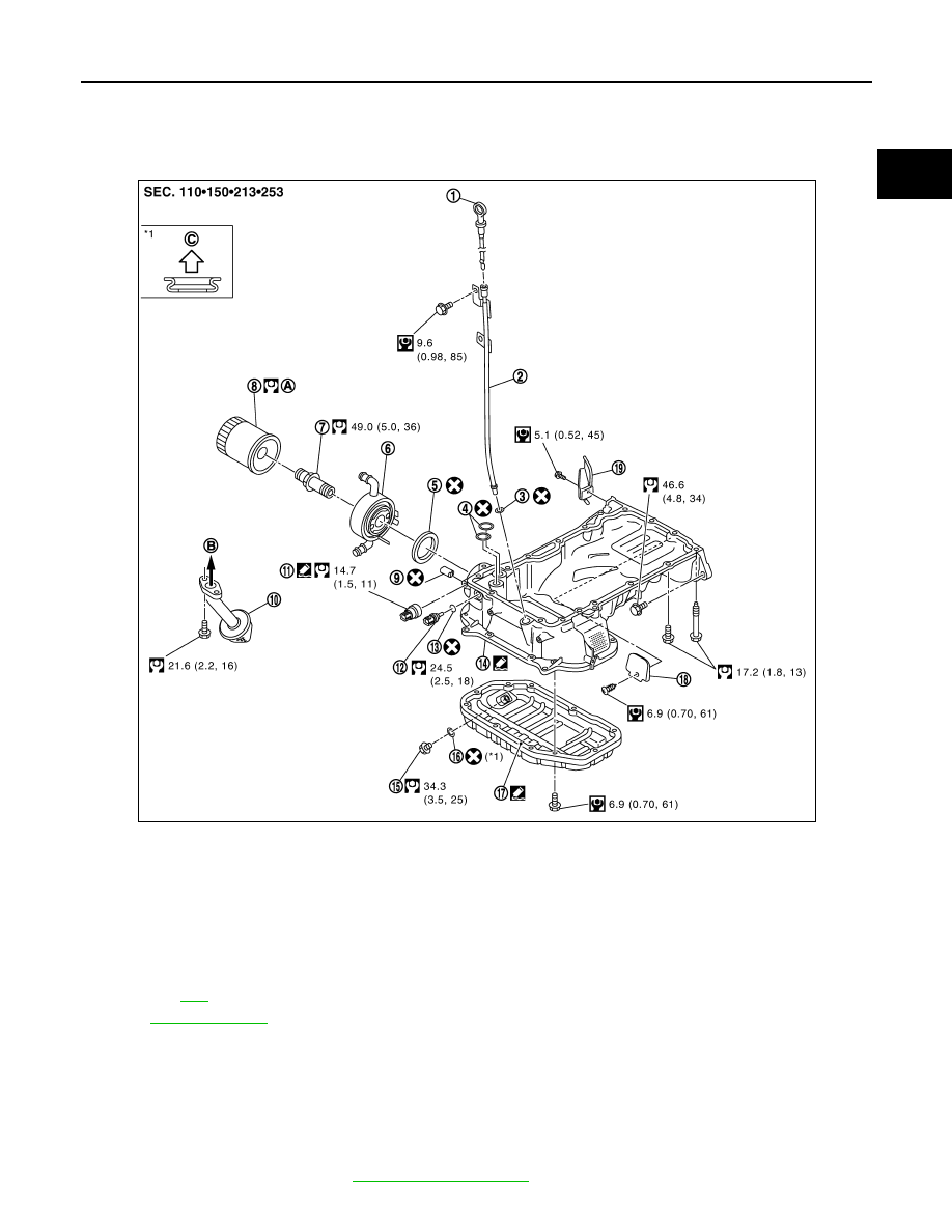
Exploded View
INFOID:0000000001547555
Disassembly and Assembly
INFOID:0000000001547556
REMOVAL
CAUTION:
Never drain engine oil when the engine is hot to avoid the danger of being scalded.
1.
Remove oil level gauge, oil pressure switch and oil temperature sensor.
2.
Remove oil pan (lower). Refer to
1.
Oil level gauge
2.
Oil level gauge guide
3.
O-ring
4.
O-ring
5.
O-ring
6.
Oil cooler
7.
Connector bolt
8.
Oil filter
9.
Relief valve
10. Oil strainer
11.
Oil pressure switch
12. Oil temperature sensor
13. Washer
14. Oil pan (upper)
15. Drain plug
16. Drain plug washer
17. Oil pan (lower)
18. Rear plate cover
19. Rear cover plate (M/T models)
A.
Refer to
B.
To oil pump
C.
Oil pan side
Refer to
for symbols in the figure.
PBIC5312E