Infiniti G37 Coupe. Manual - part 610
SPARK PLUG
EM-15
< ON-VEHICLE MAINTENANCE >
C
D
E
F
G
H
I
J
K
L
M
A
EM
N
P
O
SPARK PLUG
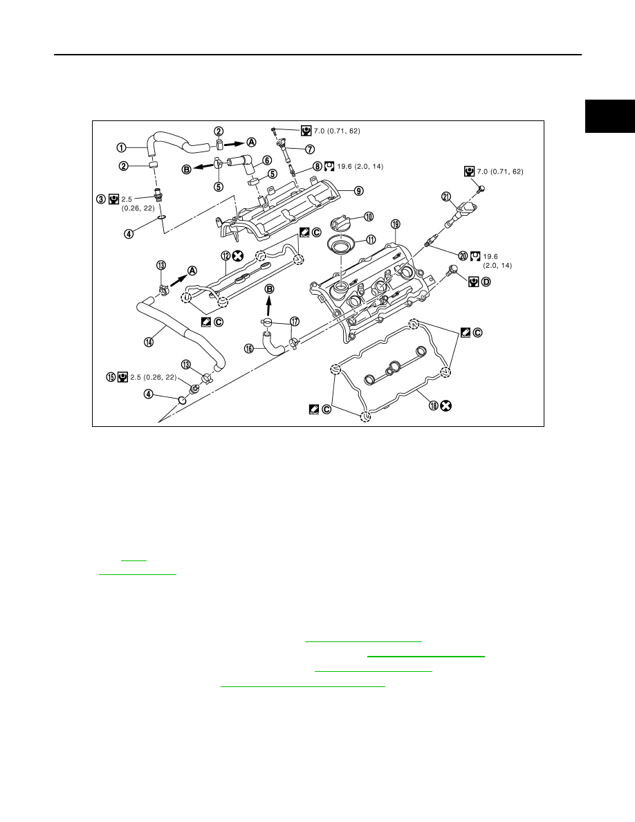
Exploded View
INFOID:0000000001547615
Removal and Installation
INFOID:0000000001547616
REMOVAL
1.
Remove engine cover with power tool. Refer to
.
2.
Remove air cleaner case and air duct (RH and LH). Refer to
.
3.
Remove electric throttle control actuator. Refer to
.
4.
Remove ignition coil. Refer to
EM-45, "Removal and Installation"
.
1.
PCV hose
2.
Clamp
3.
PCV valve
4.
O-ring
5.
Clamp
6.
PCV hose
7.
Ignition coil
8.
Spark plug
9.
Rocker cover (bank 1)
10.
Oil filler cap
11.
Oil catcher
12. Rocker cover gasket (bank 1)
13.
Clamp
14.
PCV hose
15. PCV valve
16.
PCV hose
17.
Clamp
18. Rocker cover gasket (bank 2)
19.
Rocker cover (bank 2)
20.
Spark plug
21. Ignition coil
A.
To intake manifold collector
B.
To air duct
C.
VVEL ladder assembly side
D.
Refer to
Refer to
for symbols in the figure.
JPBIA1174GB