Infiniti G37 Coupe. Manual - part 596


  Index      Infiniti     Infiniti G37 Coupe - service repair manual 2008 year


Search            


Content   ..  594  595  596  597   ..


Infiniti G37 Coupe. Manual - part 596


VVEL CONTROL MODULE

EC-565

< ECU DIAGNOSIS >

[VQ37VHR]

C

D

E

F

G

H

I

J

K

L

M

A

EC

N

P

O

VVEL CONTROL MODULE

Reference Value

INFOID:0000000001903105
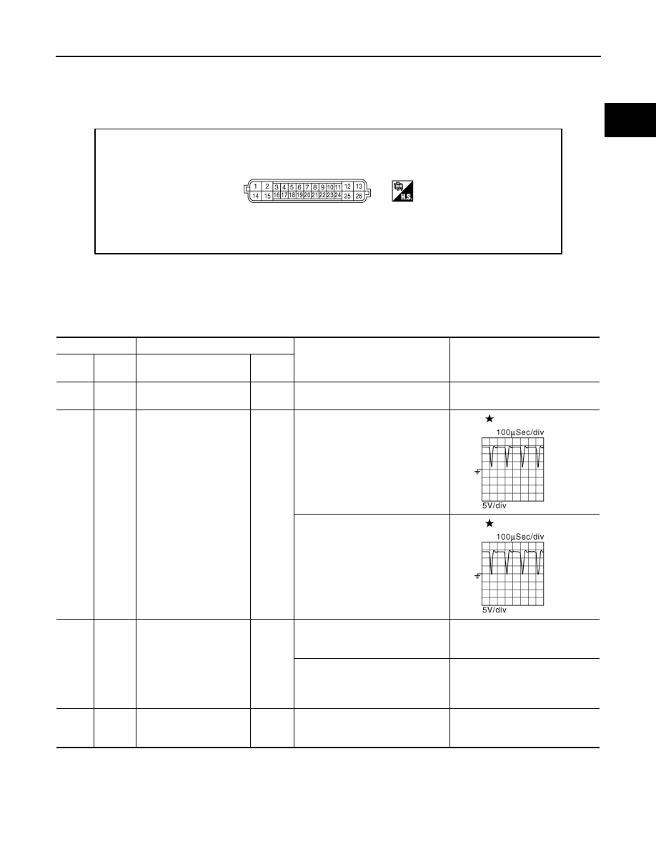
TERMINAL LAYOUT

PHYSICAL VALUES

NOTE:
• VVEL control module is located behind the IPDM E/R. For this inspection, remove hoodledge cover (RH).
• Specification data are reference values and are measured between each terminal and ground.
• Pulse signal is measured by CONSULT-III.

JMBIA0857ZZ

Terminal No.

Description

Condition

Value

(Approx.)

+

-–

Signal  name

Input/

Output

1

(W)

14

(B)

VVEL actuator motor relay 
power supply (bank 2)

Input

[Ignition switch: ON]

BATTERY VOLTAGE
(11 - 14V)

2

(L/B)

14

(B)

VVEL actuator motor 
(High lift) (bank 2)

Output

[Engine is running]
• Warm-up condition
• Idle speed

0 - 14V

[Engine is running]
• Warm-up condition
• When revving engine up to 2,000 

rpm quickly

0 - 14V

3

(G)

4

(W)

VVEL control shaft posi-
tion sensor 2 (bank 1)

Input

[Engine is running]
• Warm-up condition
• Idle speed

Approx.0.25 - 1.40V

[Engine is running]
• Warm-up condition
• When revving engine up to 2,000 

rpm quickly

Approx.0.25 - 4.75V

4

(W)

Sensor ground
[VVEL control shaft posi-
tion sensor 2 (bank 1)] 

JMBIA0854ZZ

JMBIA0855ZZ

EC-566

< ECU DIAGNOSIS >

[VQ37VHR]

VVEL CONTROL MODULE

5

(R)

6

(B)

VVEL control shaft posi-
tion sensor 2 (bank 2)

Input

[Engine is running]
• Warm-up condition
• Idle speed

Approx.0.25 - 1.40V

[Engine is running]
• Warm-up condition
• When revving engine up to 2,000 

rpm quickly

Approx.0.25 - 4.75V

6

(B)

Sensor ground
[VVEL control shaft posi-
tion sensor 2 (bank 2)] 

7

(SB)

6

(B)

Sensor power supply
[VVEL control shaft posi-
tion sensor 2 (bank 2)] 

[Ignition switch: ON]

5V

8

(O)

14

(B)

Power supply for VVEL 
control module

[Ignition switch: ON]

BATTERY VOLTAGE
(11 - 14V)

9

(LG)

4

(W)

Sensor power supply
[VVEL control shaft posi-
tion sensor 2 (bank 1)] 

[Ignition switch: ON]

5V

11

(G)

CAN communication line
[ECM]

Input/

Output

12

(G)

14

(B)

VVEL actuator motor 
(High lift) (bank 1)

Output

[Engine is running]
• Warm-up condition
• Idle speed

0 - 14V

[Engine is running]
• Warm-up condition
• When revving engine up to 2,000 

rpm quickly

0 - 14V

13

(W)

14

(B)

VVEL actuator motor relay 
power supply (bank 1)

Input

[Ignition switch: ON]

BATTERY VOLTAGE
(11 - 14V)

14

(B)

[Engine is running]
• Idle speed

Terminal No.

Description

Condition

Value

(Approx.)

+

-–

Signal name

Input/

Output

JMBIA0854ZZ

JMBIA0855ZZ

VVEL CONTROL MODULE

EC-567

< ECU DIAGNOSIS >

[VQ37VHR]

C

D

E

F

G

H

I

J

K

L

M

A

EC

N

P

O

15

(L/Y)

14

(B)

VVEL actuator motor (Low 
lift) (bank 2)

Output

[Engine is running]
• Warm-up condition
• Idle speed

0 - 14V

[Engine is running]
• Warm-up condition
• When revving engine up to 2,000 

rpm quickly

0 - 14V

16

(R)

17

(L)

VVEL control shaft posi-
tion sensor 1 (bank 1)

Input

[Engine is running]
• Warm-up condition
• Idle speed

3.50 - 4.75V

[Engine is running]
• Warm-up condition
• When revving engine up to 2,000 

rpm quickly

0.25 - 4.75V

17

(L)

Sensor ground
[VVEL control shaft posi-
tion sensor 1 (bank 1)] 

18

(G)

19

(W)

VVEL control shaft posi-
tion sensor 1 (bank 2)

Input

[Engine is running]
• Warm-up condition
• Idle speed

3.50 - 4.75V

[Engine is running]
• Warm-up condition
• When revving engine up to 2,000 

rpm quickly

0.25 - 4.75V

19

(W)

Sensor ground
[VVEL control shaft posi-
tion sensor 1 (bank 2)] 

20

(BR)

19

(W)

Sensor power supply
[VVEL control shaft posi-
tion sensor 1 (bank 2)] 

[Ignition switch: ON]

5V

21

(V)

14

(B)

VVEL actuator motor relay 
abort signal

Input

[Engine is running]
• Warm-up condition
• Idle speed

0V

22

(P)

17

(L)

Sensor power supply
[VVEL position sensor 1 
(bank 1)]

[Ignition switch: ON]

5V

23

(Y)

14

(B)

VVEL control motor relay

Output

[Ignition switch: OFF]

BATTERY VOLTAGE
(11 - 14V)

[Ignition switch: ON]

0 - 1.0V

24

(L)

CAN communication line

Input/

Output

Terminal No.

Description

Condition

Value

(Approx.)

+

-–

Signal  name

Input/

Output

JMBIA0854ZZ

JMBIA0855ZZ

EC-568

< ECU DIAGNOSIS >

[VQ37VHR]

VVEL CONTROL MODULE

: Average voltage for pulse signal (Actual pulse signal can be confirmed by oscilloscope.)

25

(BR)

14

(B)

VVEL control motor (Low 
lift) (bank 1)

Output

[Engine is running]
• Warm-up condition
• Idle speed

0 - 14V

[Engine is running]
• Warm-up condition
• When revving engine up to 2,000 

rpm quickly

0 - 14V

Terminal No.

Description

Condition

Value

(Approx.)

+

-–

Signal name

Input/

Output

JMBIA0854ZZ

JMBIA0855ZZ


Content   ..  594  595  596  597   ..