Infiniti G37 Coupe. Manual - part 474
COOLING FAN CONTROL
EC-77
< FUNCTION DIAGNOSIS >
[VQ37VHR]
C
D
E
F
G
H
I
J
K
L
M
A
EC
N
P
O
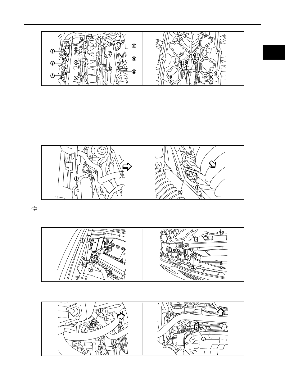
1.
Ignition coil No.5 (with power transis-
tor)
2.
Ignition coil No.3 (with power transis-
tor)
3.
Ignition coil No.1 (with power transis-
tor)
4.
Fuel injector No.3
5.
Fuel injector No.1
6.
Fuel injector No.2
7.
Fuel injector No.4
8.
Ignition coil No.2 (with power transis-
tor)
9.
Ignition coil No.4 (with power transis-
tor)
10. Ignition coil No.6 (with power transis-
tor)
11.
Fuel injector No.6
12. Fuel injector No.5
13. Knock sensor (bank 1)
14. Knock sensor (bank 2)
: Vehicle front
1.
Engine coolant temperature sensor
2.
A/F sensor 1 (bank 1)
3.
Crankshaft position sensor (POS)
1.
IPDM E/R
2.
Battery current sensor
3.
Refrigerant pressure sensor
JMBIA0843ZZ
JMBIA0844ZZ
JMBIA0013ZZ
JMBIA0014ZZ