Infiniti G37 Coupe. Manual - part 452


  Index      Infiniti     Infiniti G37 Coupe - service repair manual 2008 year


Search            


Content   ..  450  451  452  453   ..


Infiniti G37 Coupe. Manual - part 452


DLN-122

< DISASSEMBLY AND ASSEMBLY >

[REAR FINAL DRIVE: R200V]

DRIVE PINION

12. Select the correct pinion height adjusting washer.
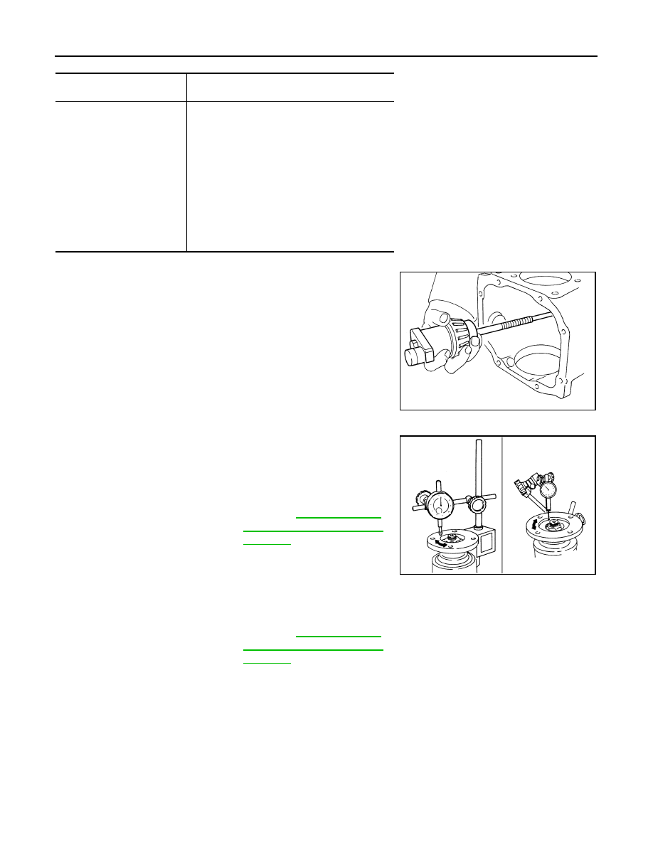
13. Remove the J-34309 differential shim selector tool from the final

drive housing. Then disassemble to retrieve the pinion bearings.

COMPANION FLANGE RUNOUT

1.

Fit a dial indicator onto the companion flange face (inner side of
the propeller shaft mounting bolt holes).

2.

Rotate the companion flange to check for runout.

3.

Fit a test indicator to the inner side of the companion flange
(socket diameter).

4.

Rotate the companion flange to check for runout.

5.

If the runout value is outside the repair limit, follow the procedure below to adjust.

a.

Check for runout while changing the phase between companion flange and drive pinion gear by 90

°

 step,

and search for the position where the runout is the minimum.

b.

If the runout value is still outside of the limit after the phase has been changed, possible causes are an
assembly malfunction of drive pinion and pinion bearing and malfunction of pinion bearing. Check for
these items and repair if necessary.

c.

If the runout value is still outside of the limit after the check and repair, replace companion flange.

Pinion head height number

Add or remove from the standard pinion height ad-

justing washer thickness measurement

 6

 5

 4

 3

 2

 1

0

+1
+2
+3
+4
+5 
+6

Add 0.06 mm (0.0024 in)
Add 0.05 mm (0.0020 in)
Add 0.04 mm (0.0016 in)
Add 0.03 mm (0.0012 in)
Add 0.02 mm (0.0008 in)
Add 0.01 mm (0.0004 in)

Use the selected washer thickness

Subtract 0.01 mm (0.0004 in)
Subtract 0.02 mm (0.0008 in)
Subtract 0.03 mm (0.0012 in)
Subtract 0.04 mm (0.0016 in)
Subtract 0.05 mm (0.0020 in)
Subtract 0.06 mm (0.0024 in)

SPD205A

Limit

Companion flange runout

: Refer to 

DLN-132, "Com-

panion flange Runout (M/T 
Models)"

.

Limit

Companion flange runout

: Refer to 

DLN-132, "Com-

panion flange Runout (M/T 
Models)"

.

JSDIA0116ZZ

DRIVE PINION

DLN-123

< DISASSEMBLY AND ASSEMBLY >

[REAR FINAL DRIVE: R200V]

C

E

F

G

H

I

J

K

L

M

A

B

DLN

N

O

P

M/T : Inspection After Disassembly

INFOID:0000000001714286

Clean up the disassembled parts. Then, inspect if the parts are worn or damaged. If so, follow the measures
below.

A/T

A/T : Exploded View

INFOID:0000000001714287

Content

Conditions and Measures

Hypoid gear

• If the gear teeth do not mesh or line-up correctly, determine the cause and adjust or replace as nec-

essary.

• If the gears are worn, cracked, damaged, pitted or chipped (by friction) noticeably, replace with new 

drive gear and drive pinion as a set.

Bearing

• If any chipped (by friction), pitted, worn, rusted or scratched mark, or unusual noise from the bearing 

is observed, replace as a bearing assembly (as a new set).

Side gear and pinion mate 
gear

• If any cracks or damage on the surface of the tooth is found, replace.
• If any worn or chipped mark on the contact sides of the thrust washer is found, replace.

Side gear thrust washer and 
pinion mate thrust washer

• If it is chipped (by friction), damaged, or unusually worn, replace.

Oil seal 

• Whenever disassembled, replace.
• If wear, deterioration of adherence (sealing force lips), or damage is detected on the lips, replace them.

Differential case

• If any wear or crack on the contact sides of the differential case is found, replace.

Companion flange

• If any chipped mark (about 0.1 mm, 0.004 in) or other damage on the contact sides of the lips of the 

companion flange is found, replace.

1.

Drive pinion lock nut

2.

Companion flange

3.

Front oil seal

4.

Pinion front bearing

5.

Gear carrier

6.

Side oil seal

JSDIA0045GB

DLN-124

< DISASSEMBLY AND ASSEMBLY >

[REAR FINAL DRIVE: R200V]

DRIVE PINION

A/T : Disassembly

INFOID:0000000001714288

1.

Remove differential case assembly. Refer to 

DLN-104, "A/T : Disassembly"

.

2.

Remove drive pinion lock nut with the flange wrench.

3.

Put matching mark (B) on the end of drive pinion. The matching
mark should be in line with the matching mark (A) on companion
flange (1).

CAUTION:

For matching mark, use paint. Never damage companion
flange and drive pinion.
NOTE:
The matching mark (A) on the final drive companion flange (1)
indicates the maximum vertical runout position.
When replacing companion flange, matching mark is not neces-
sary.

7.

Side flange

8.

Collapsible spacer

9.

Pinion rear bearing

10. Pinion height adjusting washer

11.

Drive pinion

12. Side bearing adjusting washer

13. Side bearing

14. Drive gear

15. Differential case B

16. Side gear thrust washer

17. Circular clip

18. Side gear

19. Pinion mate shaft

20. Pinion mate thrust washer

21. Pinion mate gear

22. Viscous coupling

23. Differential case A

24. Bearing cap

25. Filler plug

26. Gasket

27. Rear cover

28. Drain plug

A.

Oil seal lip

B.

 Screw hole

C.

After tightening the bolts to the spec-
ified torque, tighten the bolts addi-
tionally by turning the bolts 31 to 36 
degrees.

:

Apply gear oil.

:

Apply anti-corrosion oil.

:

Apply Genuine Silicone RTV or equivalent. Refer to 

GI-15, "Recommended Chemical Products and Sealants"

.

:

Apply Genuine High Strength Thread Locking Sealant or equivalent. Refer to 

GI-15, "Recommended Chemical Products 

and Sealants"

.

Refer to 

GI-4, "Components"

 for symbols not described on the above.

JSDIA0033ZZ

JSDIA0016ZZ

DRIVE PINION

DLN-125

< DISASSEMBLY AND ASSEMBLY >

[REAR FINAL DRIVE: R200V]

C

E

F

G

H

I

J

K

L

M

A

B

DLN

N

O

P

4.

Remove companion flange using the suitable pullers.

5.

Press drive pinion assembly out of gear carrier.

CAUTION:

Never drop drive pinion assembly.

6.

Remove front oil seal.

7.

Remove side oil seal.

8.

Remove pinion front bearing inner race.

9.

Remove collapsible spacer.

10. Remove pinion rear bearing inner race and pinion height adjust-

ing washer with the replacer (A).

11. Tap pinion front/rear bearing outer races uniformly using a brass

rod or equivalent to remove them.

CAUTION:

Never damage gear carrier.

JSDIA0034ZZ

PDIA0760J

PDIA0801J

SDIA0817E


Content   ..  450  451  452  453   ..