Infiniti G37 Coupe. Manual - part 376


  Index      Infiniti     Infiniti G37 Coupe - service repair manual 2008 year


Search            


Content   ..  374  375  376  377   ..


Infiniti G37 Coupe. Manual - part 376


POWER SUPPLY AND GROUND CIRCUIT

DLK-65

< COMPONENT DIAGNOSIS >

[INTELLIGENT KEY SYSTEM]

C

D

E

F

G

H

I

J

L

M

A

B

DLK

N

O

P

POWER SUPPLY AND GROUND CIRCUIT

Diagnosis Procedure

INFOID:0000000001683058

1.

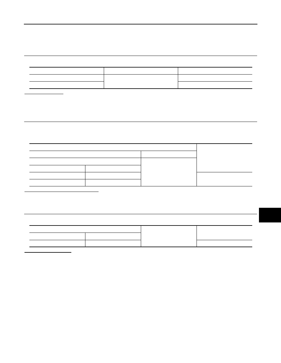
CHECK FUSE AND FUSIBLE LINK

Check that the following fuse and fusible link are not blown.

Is the fuse blown?

YES

>> Replace the blown fuse or fusible link after repairing the affected circuit if a fuse or fusible link is

blown.

NO

>> GO TO 2.

2.

CHECK POWER SUPPLY CIRCUIT

1.

Turn ignition switch OFF.

2.

Disconnect BCM connectors.

3.

Check voltage between BCM harness connector and ground.

Is the measurement value normal?

YES

>> GO TO 3.

NO

>> Repair or replace harness or connector.

3.

CHECK GROUND CIRCUIT

Check continuity between BCM harness connector and ground.

Does continuity exist?

YES

>> INSPECTION END

NO

>> Repair or replace harness or connector.

Terminal No.

Signal name

Fuse and fusible link No.

1

Battery power supply

K

11

10

Terminals

Voltage

(Approx.)

(+)

(

)

BCM

Ground

Connector

Terminal

M118

1

Battery voltage

M119

11

BCM

Ground

Continuity

Connector

Terminal

M119

13

Existed

DLK-66

< COMPONENT DIAGNOSIS >

[INTELLIGENT KEY SYSTEM]

DOOR SWITCH

DOOR SWITCH

Description

INFOID:0000000001683059

Detects door open/close condition.

Component Function Check

INFOID:0000000001683060

1.

CHECK FUNCTION

With CONSULT-III

Check door switches (“DOOR SW-DR”, “DOOR SW-AS”) in Data Monitor” mode with CONSULT-III.

Is the inspection result normal?

YES

>> Door switch is OK.

NO

>> Refer to 

DLK-66, "Diagnosis Procedure"

.

Diagnosis Procedure

INFOID:0000000001683061

1.

CHECK DOOR SWITCH INPUT SIGNAL

1.

Turn ignition switch OFF.

2.

Check signal between BCM harness connector and ground with oscilloscope.

Is the inspection result normal?

YES

>> GO TO 4.

NO

>> GO TO 2.

2.

CHECK DOOR SWITCH CIRCUIT 

1.

Disconnect BCM connector and door switch connector.

2.

Check continuity between BCM harness connector and door switch harness connector.

Monitor item

Condition

DOOR SW-DR

CLOSE 

 OPEN: OFF 

 ON

DOOR SW-AS

Terminals

Door condition

Voltage (V)

(Approx.)

(+)

(–)

BCM

connector

Terminal

M123

150

Ground

Driver side

OPEN

0

CLOSE

124

Passenger side

OPEN

0

CLOSE

JPMIA0011GB

JPMIA0011GB

DOOR SWITCH

DLK-67

< COMPONENT DIAGNOSIS >

[INTELLIGENT KEY SYSTEM]

C

D

E

F

G

H

I

J

L

M

A

B

DLK

N

O

P

3.

Check continuity between BCM harness connector and ground.

Is the inspection result normal?

YES

>> GO TO 3.

NO

>> Repair or replace harness between BCM and door switch.

3.

CHECK DOOR SWITCH 

Refer to 

DLK-67, "Component Inspection"

.

Is the inspection result normal?

YES

>> GO TO 4.

NO

>> Replace malfunctioning door switch. Refer to 

DLK-238, "Removal and Installation"

.

4.

CHECK INTERMITTENT INCIDENT

Refer to 

GI-38, "Intermittent Incident"

.

>> INSPECTION END 

Component Inspection

INFOID:0000000001683062

1.

CHECK DOOR SWITCH

1.

Turn ignition switch OFF.

2.

Disconnect door switch connector.

3.

Check continuity between door switch terminal and ground.

Is the inspection result normal?

YES

>> INSPECTION END

NO

>> Replace malfunctioning door switch. Refer to 

DLK-238, "Removal and Installation"

.

BCM connector

Terminal

Door switch

connector

Terminal

Continuity 

M123

150

B16 (Driver side)

2

Existed

124

B216 (Passenger side)

BCM connector

Terminal

Ground

Continuity 

M123

150

Not existed

124

Terminal

Door switch condition

Continuity

Door switch

2

Ground part of door switch

Pressed

Not existed

Released

Existed

DLK-68

< COMPONENT DIAGNOSIS >

[INTELLIGENT KEY SYSTEM]

DOOR LOCK AND UNLOCK SWITCH

DOOR LOCK AND UNLOCK SWITCH

DRIVER SIDE

DRIVER SIDE : Description

INFOID:0000000001683063

Transmits door lock/unlock operation to BCM.

DRIVER SIDE : Component Function Check

INFOID:0000000001683064

1.

CHECK FUNCTION

With CONSULT-III

Check door lock and unlock switch (“CDL LOCK SW ”, “CDL UNLOCK SW”) in Data Monitor mode with CON-
SULT-III.

Is the inspection result normal?

YES

>> Door lock and unlock switch is OK.

NO

>> Refer to 

DLK-68, "DRIVER SIDE : Diagnosis Procedure"

.

DRIVER SIDE : Diagnosis Procedure

INFOID:0000000001879565

1.

CHECK POWER WINDOW SWITCH OUTPUT SIGNAL

1.

Door of driver side and passenger side is closed.

2.

Check signal between BCM harness connector and ground with oscilloscope when door lock and unlock
switch (driver side) is turned to “LOCK” or “UNLOCK”.

3.

Check that signals which are shown in the figure below can be detected during 10 seconds just after door
lock and unlock switch (driver side) is turned to “LOCK” or “UNLOCK”.

Is the inspection result normal?

YES

>> GO TO 4.

NO

>> GO TO 2.

2.

CHECK POWER WINDOW SWITCH GROUND

1.

Turn ignition switch OFF.

2.

Disconnect power window main switch connector.

3.

Check continuity between power window main switch harness connector and ground.

Is the inspection result normal?

Monitor item

Condition

CDL LOCK SW 

LOCK

: ON

UNLOCK

: OFF

CDL UNLOCK SW 

LOCK

: OFF

UNLOCK

: ON

Terminal

Signal

(Reference value)

(+)

(–)

BCM connector

Terminal 

M123

132

Ground

JPMIA0013GB

Power window main switch connector

Description

Continuity

D8

15

Ground

Existed


Content   ..  374  375  376  377   ..