Infiniti G37 Coupe. Manual - part 343
CO-22
< ON-VEHICLE REPAIR >
WATER INLET AND THERMOSTAT ASSEMBLY
WATER INLET AND THERMOSTAT ASSEMBLY
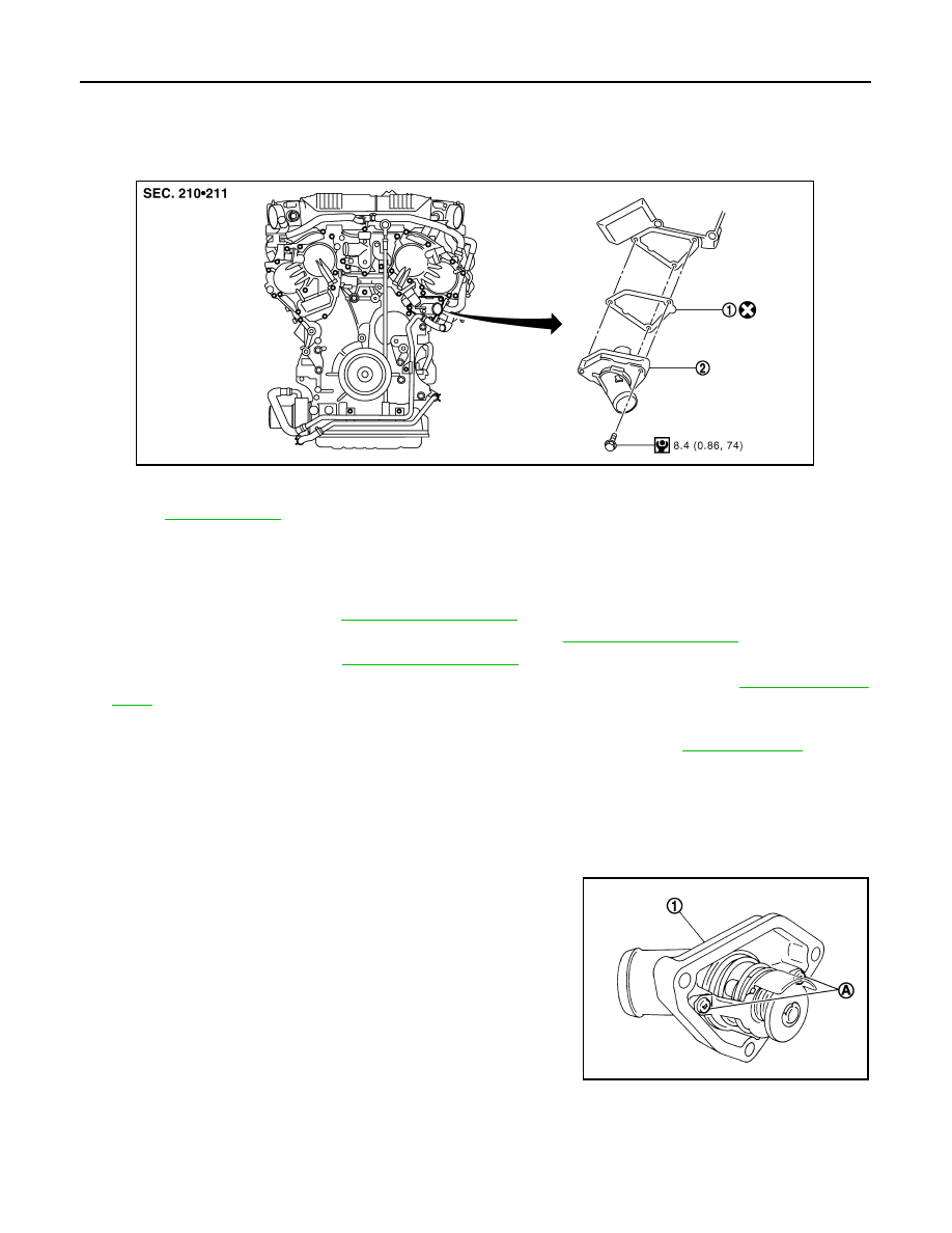
Exploded View
INFOID:0000000001547674
Removal and Installation
INFOID:0000000001547675
REMOVAL
1.
Remove engine cover. Refer to
2.
Remove air duct and air cleaner case assembly (LH). Refer to
.
3.
Remove reservoir tank.Refer to
4.
Remove oil cooler water pipe mounting bolt, and move aside water pipe. Refer to
.
5.
Remove engine undercover with power tool.
6.
Drain engine coolant from radiator drain plug at the bottom of radiator. Refer to
CAUTION:
• Perform this step when the engine is cold.
• Never spill engine coolant on drive belts.
7.
Disconnect radiator hose (lower).
8.
Disconnect intake valve timing control valve harness connector (LH), and remove intake valve timing con-
trol solenoid.
9.
Remove water inlet and thermostat assembly (1).
CAUTION:
Never disassemble water inlet and thermostat assembly.
Replace them as a unit, if necessary.
INSTALLATION
Note the following, and install in the reverse order of removal.
• Be careful not to spill engine coolant over engine room. Use rag to absorb engine coolant.
1.
Gasket
2.
Water inlet and thermostat assembly
Refer to
for symbols in the figure.
JPBIA1201GB
A
: Do not loosen these screw.
JPBIA0261ZZ