Infiniti G37 Coupe. Manual - part 253


  Index      Infiniti     Infiniti G37 Coupe - service repair manual 2008 year


Search            


Content   ..  251  252  253  254   ..


Infiniti G37 Coupe. Manual - part 253


BR-50

< ON-VEHICLE REPAIR >

FRONT DISC BRAKE

2.

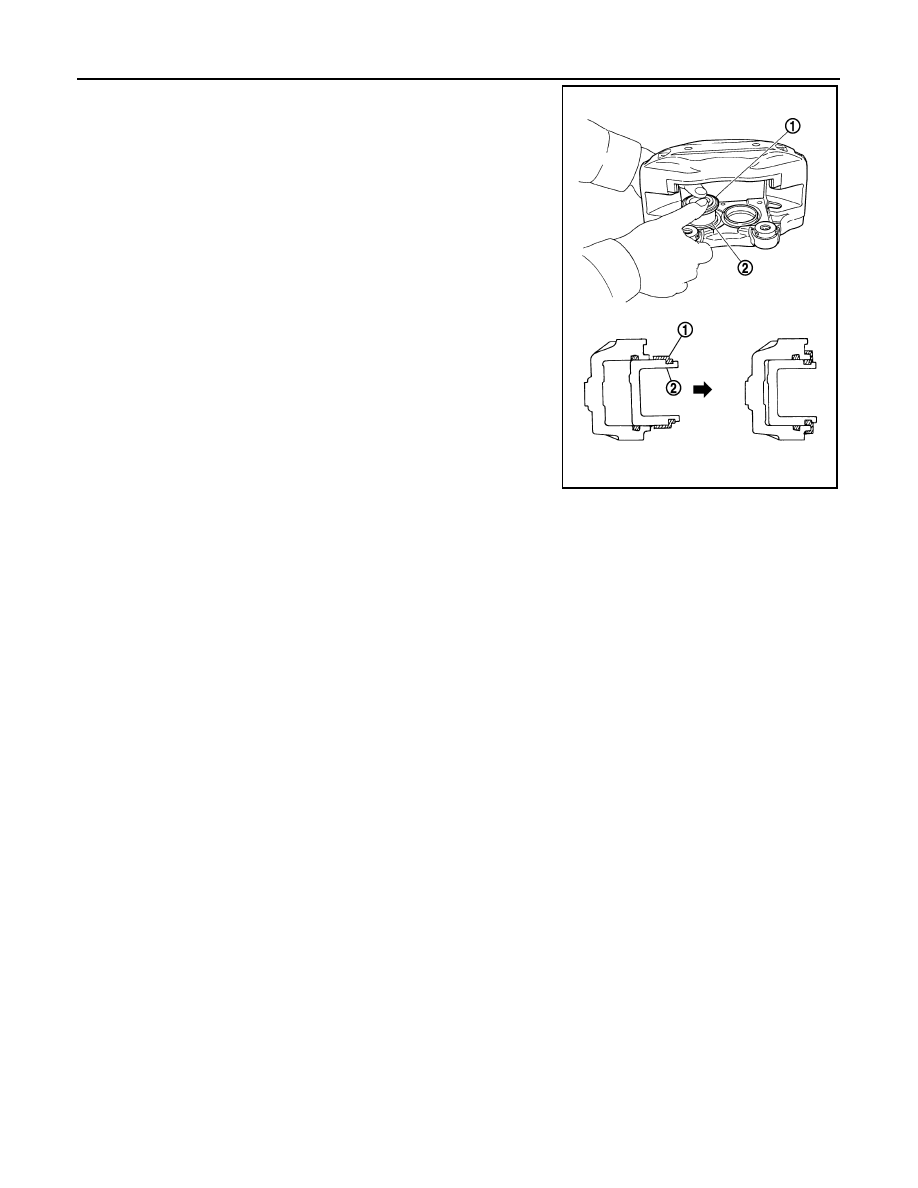
Apply rubber grease to piston boots (1). Cover the piston (2) end
with piston boots, and then install caliper side lip on piston boot
securely into a groove on caliper.

CAUTION:

Never reuse piston boots.

3.

Apply brake fluid to piston. Push piston into caliper by hand and
push piston boot piston-side lip into the piston groove.

CAUTION:

Press the piston evenly and vary the pressing point to pre-
vent caliper inner wall from being rubbed.

4.

Install the caliper to tighten the caliper mounting bolts to the
specified torque.

BRAKE CALIPER ASSEMBLY (4 PISTON TYPE) : Inspection and Adjustment

INFOID:0000000001647877

INSPECTION AFTER DISASSEMBLY

Caliper

Check the inner wall of the caliper for rust, wear, cracks or damage. Replace the caliper if any abnormal con-
dition is detected.

CAUTION:

Always clean with new brake fluid. Never clean with mineral oil such as gasoline and light oil.

Pistons

Check the surface of the piston for rust, wear, cracks or damage. Replace the piston if any abnormal condition
is detected.

CAUTION:

A piston sliding surface is plated. Never polish with sandpaper.

ADJUSTMENT AFTER INSTALLATION

Brake Burnishing Procedure

Burnish contact surfaces between disc rotors and pads according to following procedure after refinishing or
replacing disc rotor, or if a soft pedal occurs at very low mileage.

CAUTION:

• Be careful of vehicle speed because the brake does not operate easily until pad and disc rotor are

securely fitted.

• Only perform this procedure under safe road and traffic conditions. Use extreme caution.
1.

Drive vehicle on straight, flat road.

2.

Depress brake pedal with the power to stop vehicle within 3 to 5 seconds until the vehicle stops.

3.

Drive without depressing brake for a few minutes to cool the brake.

4.

Repeat steps 1 to 3 until pad and disc rotor are securely fitted.

PFIA0905J

REAR DISC BRAKE

BR-51

< ON-VEHICLE REPAIR >

C

D

E

G

H

I

J

K

L

M

A

B

BR

N

O

P

REAR DISC BRAKE

BRAKE PAD (1 PISTON TYPE)

BRAKE PAD (1 PISTON TYPE) : Exploded View

INFOID:0000000001824833

BRAKE PAD (1 PISTON TYPE) : Removal and Installation

INFOID:0000000001647879

REMOVAL

WARNING:

Clean any dust from the brake caliper and brake pads with a vacuum dust collector. Never blow with
compressed air.

CAUTION:

• Never depress the brake pedal while removing the brake pads or the cylinder body because the pis-

ton may pop out.

• Never spill or splash brake fluid on the disc rotor.

1.

Brake hose

2.

Union bolt

3.

Copper washer

4.

Cap

5.

Bleeder valve

6.

Sliding pin bolt

7.

Cylinder body

8.

Piston seal

9.

Piston

10.

Piston boot

11. Sliding pin boot

12.

Bushing

13.

Torque member

14. Inner shim cover

15.

Inner shim

16.

Inner pad

17. Pad wear sensor (RH inner pad 

only)

18.

Pad retainer

19.

Outer pad

20. Outer shim

 1: Apply rubber grease.

 2: Apply PBC (Poly Butyl Cuprysil) grease or silicone-based grease.

 3: Apply polyglycol ether based lubricant.

: Apply brake fluid.

Refer to 

GI-4, "Components"

 for symbols not described on the above.

JPFIA0064GB

BR-52

< ON-VEHICLE REPAIR >

REAR DISC BRAKE

1.

Remove tires with power tool.

2.

Remove the upper sliding pin bolt.

3.

Suspend the cylinder body with suitable wire so that the brake hose will not stretch. Remove the brake
pads from the torque member.

CAUTION:

• Never deform the pad retainers if removing the pad retainers.
• Never damage the piston boot.
• Never drop the brake pad, shims, and the shim cover.

INSTALLATION

WARNING:

Clean any dust from the brake caliper and brake pads with a vacuum dust collector. Never blow with
compressed air.

CAUTION:

• Never depress the brake pedal while removing the brake pads or the cylinder body because the pis-

ton may pop out.

• Never spill or splash brake fluid on the disc rotor.

1.

Apply PBC (Poly Butyl Cuprysil) grease or silicone-based grease to the pad retainers before installing it to
the torque member if the pad retainers has been removed.

CAUTION:

• Securely assemble the pad retainers so that it will not be lifted up from the torque member.
• Never deform the pad retainers.

2.

Apply PBC (Poly Butyl Cuprysil) grease or silicone-based grease to the mating faces between the shims
and the shim cover and install them to the brake pad.

CAUTION:

Always replace the shims together with the shim cover when replacing the brake pad.

3.

Install cylinder body and brake pads to torque member.

CAUTION:

• Never damage the piston boot.
• In the case of replacing a pads with new one, check a brake fluid level in the reservoir tank

because brake fluid returns to master cylinder reservoir tank when pressing piston in.

NOTE:
Use a disc brake piston tool to easily press piston. 

4.

Install the upper sliding pin bolt and tighten it to the specified torque.

5.

Depress the brake pedal several times to check that no drag feel is present for the rear disc brake.

6.

Install tires.

BRAKE PAD (1 PISTON TYPE) : Inspection and Adjustment

INFOID:0000000001647880

INSPECTION AFTER REMOVAL

Replace the shims and the shim cover if rust is excessively attached.

ADJUSTMENT AFTER INSTALLATION

Brake Burnishing Procedure

Burnish contact surfaces between pads according to following procedure after refinishing or replacing pads, or
if a soft pedal occurs at very low mileage.

CAUTION:

• Be careful of vehicle speed because the brake does not operate easily until pad and disc rotor are

securely fitted.

• Only perform this procedure under safe road and traffic conditions. Use extreme caution.

1.

Drive vehicle on straight, flat road.

2.

Depress brake pedal with the power to stop vehicle within 3 to 5 seconds until the vehicle stops.

3.

Drive without depressing brake for a few minutes to cool the brake.

4.

Repeat steps 1 to 3 until pad and disc rotor are securely fitted.

BRAKE PAD (2 PISTON TYPE)

REAR DISC BRAKE

BR-53

< ON-VEHICLE REPAIR >

C

D

E

G

H

I

J

K

L

M

A

B

BR

N

O

P

BRAKE PAD (2 PISTON TYPE) : Exploded View

INFOID:0000000001647955

BRAKE PAD (2 PISTON TYPE) : Removal and Installation

INFOID:0000000001647882

REMOVAL

WARNING:

Clean any dust from the brake caliper and brake pads with a vacuum dust collector. Never blow with
compressed air.

CAUTION:

• Never depress the brake pedal while removing the brake pads or the cylinder body because the pis-

ton may pop out.

• Never spill or splash brake fluid on the disc rotor.

1.

Remove tires with power tool.

1.

Piston

2.

Piston seal

3.

Piston boot

4.

Retaining ring

5.

Cap

6.

Bleeder valve

7.

Cap

8.

Clip

9.

Pad pin

10.

Caliper

11. Inner shim cover

12.

Inner shim

13.

Inner pad

14. Pad wear sensor (RH inner pad 

only)

15.

Cross spring

16.

Outer pad

17. Outer shim

18.

Outer shim cover

 1: Apply rubber grease.

 2: Apply copper based brake grease.

: Apply brake fluid.

Refer to 

GI-4, "Components"

 for symbols not described on the above.

JPFIA0219GB


Content   ..  251  252  253  254   ..