Infiniti G37 Coupe. Manual - part 234
BCS-54
< ECU DIAGNOSIS >
BCM (BODY CONTROL MODULE)
74
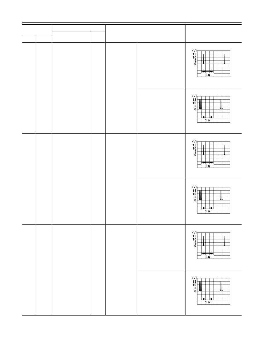
(SB)
Ground
Passenger door an-
tenna (-)
Output
When the pas-
senger door re-
quest switch is
operated with ig-
nition switch OFF
When Intelligent Key is in
the antenna detection area
When Intelligent Key is not
in the antenna detection
area
75
(BR)
Ground
Passenger door an-
tenna (+)
Output
When the pas-
senger door re-
quest switch is
operated with ig-
nition switch OFF
When Intelligent Key is in
the antenna detection area
When Intelligent Key is not
in the antenna detection
area
76
(V)
Ground
Driver door antenna
(-)
Output
When the driver
door request
switch is operat-
ed with ignition
switch OFF
When Intelligent Key is in
the antenna detection area
When Intelligent Key is not
in the antenna detection
area
Terminal No.
(Wire color)
Description
Condition
Value
(Approx.)
Signal name
Input/
Output
+
–
JMKIA0062GB
JMKIA0063GB
JMKIA0062GB
JMKIA0063GB
JMKIA0062GB
JMKIA0063GB