Infiniti G37 Coupe. Manual - part 223
BCS-10
< FUNCTION DIAGNOSIS >
POWER CONSUMPTION CONTROL SYSTEM
POWER CONSUMPTION CONTROL SYSTEM
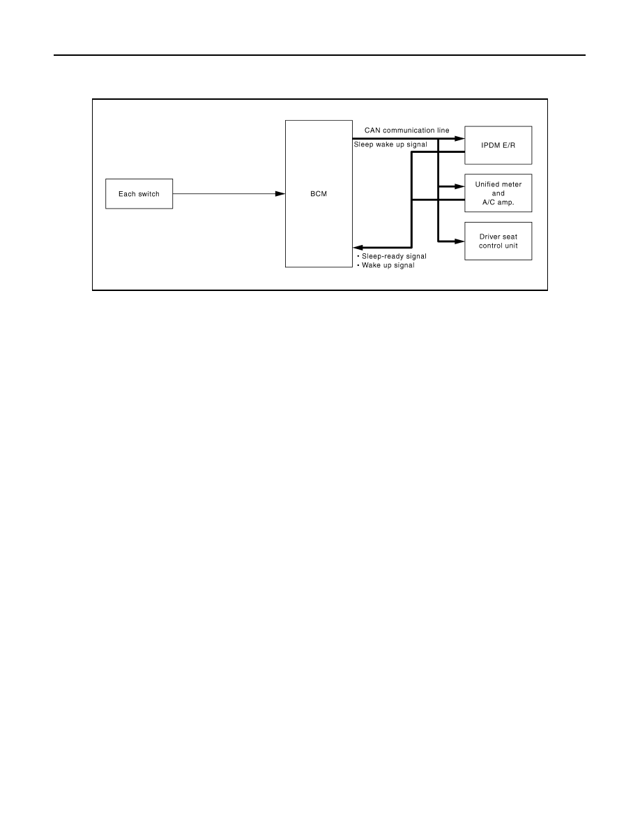
System Diagram
INFOID:0000000001612377
System Description
INFOID:0000000001612378
OUTLINE
• BCM incorporates a power saving control function that reduces the power consumption according to the
vehicle status.
• BCM switches the status (control mode) by itself with the power saving control function. It performs the sleep
request to each unit [IPDM E/R, combination meter (unified meter and A/C amp.) and driver seat control unit]
that operates with the ignition switch OFF.
Normal mode (wake-up)
- CAN communication is normally performed with other units
- Each control with BCM is operating properly
CAN communication sleep mode (CAN sleep)
- CAN transmission is stopped
- Control with BCM only is operating
Low power consumption mode (BCM sleep)
- Low power consumption control is active
- CAN transmission is stopped
LOW POWER CONSUMPTION CONTROL WITH BCM
BCM reduces the power consumption with the following operation in the low power consumption mode.
• The reading interval of the each switches changes from 10 ms interval to 60 ms interval.
Sleep mode activation
• BCM receives the sleep-ready signal (ready) from IPDM E/R and unified meter and A/C amp. via CAN com-
munication.
• BCM transmits the sleep wake up signal (sleep) to each unit when all of the CAN sleep conditions are ful-
filled.
• Each unit stops the transmission of CAN communication with the sleep wake up signal. BCM is in CAN com-
munication sleep mode.
• BCM is in the low power consumption mode and perform the low power consumption control when all of the
BCM sleep conditions are fulfilled with CAN sleep condition.
JPMIA0069GB