Infiniti G37 Coupe. Manual - part 178
AV
AV CONTROL UNIT
AV-465
< ECU DIAGNOSIS >
[BOSE AUDIO WITH NAVIGATION]
C
D
E
F
G
H
I
J
K
L
M
B
A
O
P
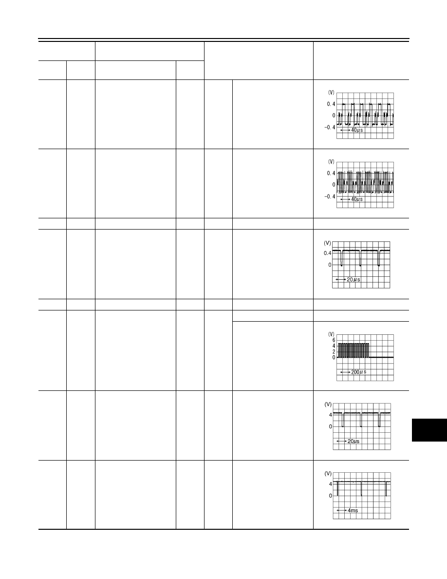
62
(B)
Ground
RGB signal (G: green)
Output
Ignition
switch
ON
Start confirmation/adjust-
ment mode, and then dis-
play color bar by selecting
“Color Spectrum Bar” on
DISPLAY DIAGNOSIS
screen.
63
(R)
Ground
RGB signal (B: blue)
Output
Ignition
switch
ON
Start confirmation/adjust-
ment mode, and then dis-
play color bar by selecting
“Color Spectrum Bar” on
DISPLAY DIAGNOSIS
screen.
64
—
Shield
—
—
—
—
65
(G)
Ground
RGB synchronizing signal
Output
Ignition
switch
ON
—
66
—
Shield
—
—
—
—
67
(B)
*1
(L)
*2
Ground
RGB area (YS) signal
Output
Ignition
switch
ON
At RGB image displayed
5 V
At rear view camera image
is displayed
68
(R)
Ground
Horizontal synchronizing
(HP) signal
Input
Ignition
switch
ON
—
69
(W)
Ground
Vertical synchronizing (VP)
signal
Input
Ignition
switch
ON
—
Terminal
(Wire color)
Description
Condition
Reference value
(Approx.)
+
–
Signal name
Input/
Output
SKIB2236J
SKIB2237J
JPNIA0461GB
PKIB4948J
SKIB3601E
SKIB3598E