Infiniti G37 Coupe. Manual - part 159
AV
DIAGNOSIS SYSTEM (AV CONTROL UNIT)
AV-389
< FUNCTION DIAGNOSIS >
[BOSE AUDIO WITH NAVIGATION]
C
D
E
F
G
H
I
J
K
L
M
B
A
O
P
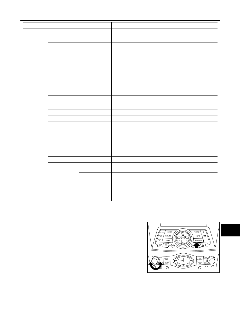
STARTING PROCEDURE
1.
Start the engine.
2.
Turn the audio system OFF.
3.
While pressing the “SETTING” button, turn the volume control
dial clockwise or counterclockwise for 40 clicks or more. (When
the self-diagnosis mode is started, a short beep will be heard.)
• Shifting from current screen to previous screen is performed
by pressing “BACK” button.
Confirmation/
Adjustment
Display Diagnosis
The following check functions are available: color tone check by color
bar display, light and shade check by gray scale display and touch pan-
el calibration response check.
Vehicle Signals
Diagnosis of signals can be performed for vehicle speed, parking
brake, lights, ignition switch, and reverse.
Speaker Test
The connection of a speaker can be confirmed by test tone.
Climate Control
Start auto air conditioner system self-diagnosis.
Navigation
Steering Angle Ad-
justment
When there is a difference between the actual turning angle and the ve-
hicle mark turning angle, it can be adjusted.
Speed Calibration
When there is a difference between the current location mark and the
actual location, it can be adjusted.
XM SAT Subscrip-
tion Status
The XM NavTraffic subscription status can be checked.
Error History
The system malfunction and the frequency when occurring in the past
are displayed. When the malfunctioning item is selected, the time and
place that the selected malfunction last occurred are displayed.
Synchronizer FES clock
–
Vehicle CAN Diagnosis
The transmitting/receiving of CAN communication can be monitored.
AV COMM Diagnosis
The communication condition of each unit of Multi AV system can be
monitored.
Handsfree Phone
The received volume adjustment of hands-free phone, microphone
speaker check, and erase memory can be performed.
Camera Cont.
The signal connected to camera control unit can be checked and the
guiding line position that overlaps rear view camera image can be ad-
justed.
Bluetooth
The passkey and the device name can be checked and changed.
SAT
Change Channel
Any necessary channels required to receive traffic information from the
satellite radio system can be set.
Change Application
ID
Any application ID's required to receive traffic information from the sat-
ellite radio system can be set.
Diag
Not used.
Delete Unit Connection Log
Erase the connection history of unit and error history.
Initialize Settings
Initializes the AV control unit memory.
Mode
Description
JSNIA0060GB