Infiniti G37 Coupe. Manual - part 1355


  Index      Infiniti     Infiniti G37 Coupe - service repair manual 2008 year


Search            


Content   ..  1353  1354  1355  1356   ..


Infiniti G37 Coupe. Manual - part 1355


TRANSMISSION ASSEMBLY

TM-273

< DISASSEMBLY AND ASSEMBLY >

[5AT: RE5R05A]

C

E

F

G

H

I

J

K

L

M

A

B

TM

N

O

P

Disassembly

INFOID:0000000001672297

CAUTION:

Do not disassemble parts behind Drum Support. Refer to 
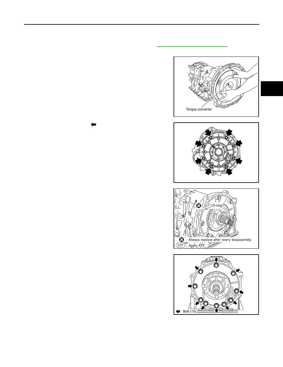
TM-91, "Cross-Sectional View"

.

1.

Drain ATF through drain plug.

2.

Remove torque converter by holding it firmly and turning while
pulling straight out.

3.

Remove tightening bolts (

) for converter housing and trans-

mission case.

4.

Remove converter housing from transmission case.

CAUTION:

Be careful not to scratch converter housing.

5.

Remove O-ring from input clutch assembly.

6.

Remove tightening bolts for oil pump assembly and transmis-
sion case.

SCIA5010E

SCIA8096E

SCIA5011E

SCIA2300E

TM-274

< DISASSEMBLY AND ASSEMBLY >

[5AT: RE5R05A]

TRANSMISSION ASSEMBLY

7.

Attach the sliding hammers to oil pump assembly and extract it
evenly from transmission case.

CAUTION:

• Fully tighten the sliding hammer screws.
• Make sure that bearing race is installed to the oil pump

assembly edge surface.

8.

Remove O-ring from oil pump assembly.

9.

Remove bearing race from oil pump assembly.

10. Remove needle bearing from front sun gear.

SCIA5474E

SCIA5172E

SCIA6529E

SCIA2808E

TRANSMISSION ASSEMBLY

TM-275

< DISASSEMBLY AND ASSEMBLY >

[5AT: RE5R05A]

C

E

F

G

H

I

J

K

L

M

A

B

TM

N

O

P

11. Remove front sun gear assembly from front carrier assembly.

NOTE:
Remove front sun gear by rotating left/right.

12. Remove seal rings from input clutch assembly.

13. Remove front carrier assembly from rear carrier assembly. (With

input clutch assembly and rear internal gear.)

CAUTION:

Be careful to remove it with needle bearing.

14. Loosen lock nut and remove band servo anchor end pin from

transmission case.

15. Remove brake band from transmission case.

SCIA5014E

SCIA2470E

SCIA5015E

SCIA6512E

SCIA2580E

TM-276

< DISASSEMBLY AND ASSEMBLY >

[5AT: RE5R05A]

TRANSMISSION ASSEMBLY

• To prevent brake linings from cracking or peeling, do not

stretch the flexible band unnecessarily. When removing
the brake band, always secure it with a clip as shown in
the figure at right.
Leave the clip in position after removing the brake band.

• Check brake band facing for damage, cracks, wear or

burns.

16. Remove mid carrier assembly and rear carrier assembly as a

unit.

17. Remove mid carrier assembly from rear carrier assembly.

18. Remove needle bearing (front side) from mid carrier assembly.

19. Remove needle bearing (rear side) from mid carrier assembly.

SAT655

SCIA5017E

SCIA5697E

SCIA2805E

SCIA2804E


Content   ..  1353  1354  1355  1356   ..