Content .. 1347 1348 1349 1350 ..
Infiniti G37 Coupe. Manual - part 1349
PARKING COMPONENTS
TM-249
< ON-VEHICLE REPAIR >
[5AT: RE5R05A]
C
E
F
G
H
I
J
K
L
M
A
B
TM
N
O
P
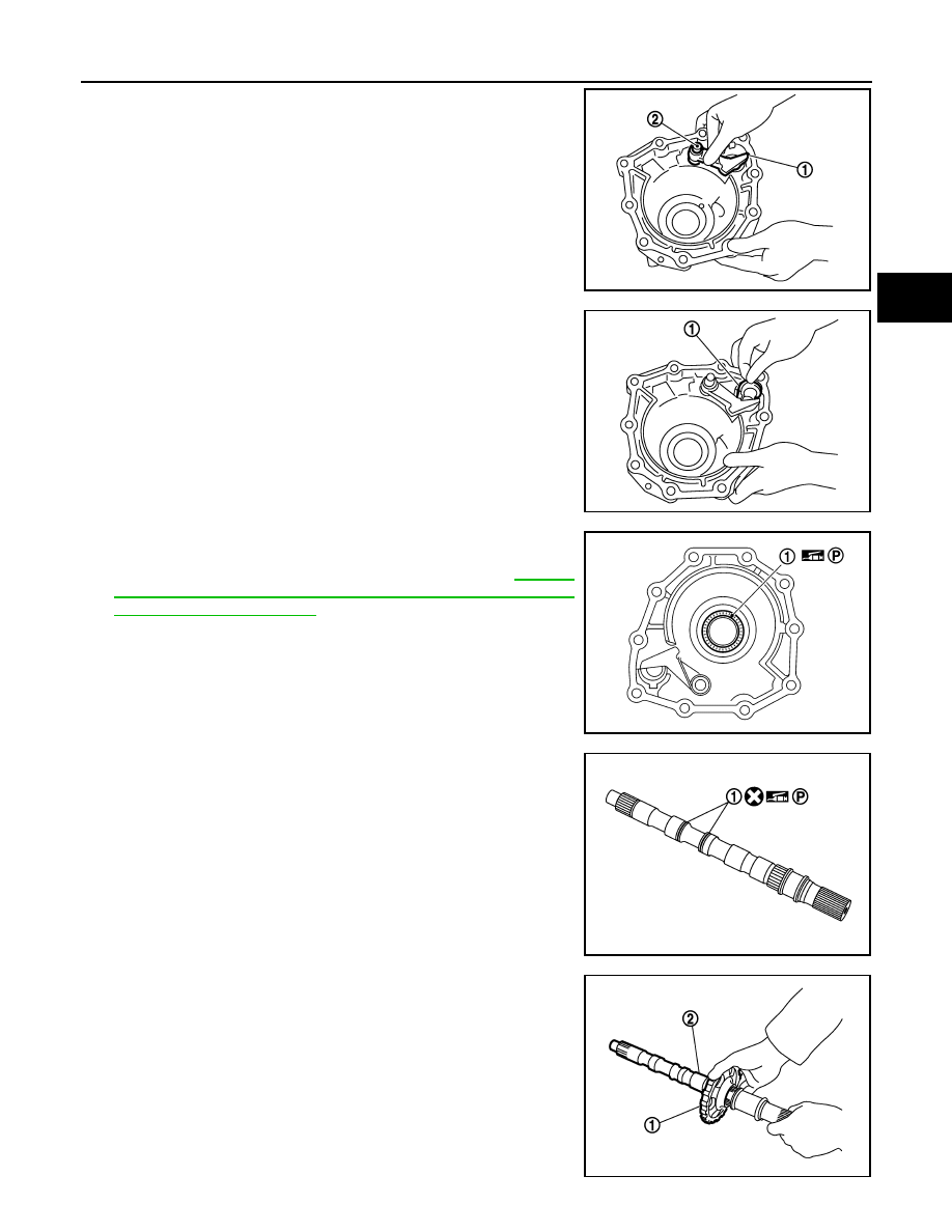
3.
Install parking pawl (with return spring) (1) and pawl shaft (2) to
rear extension.
4.
Install parking actuator support (1) to rear extension.
5.
Install bearing (1) to rear extension.
CAUTION:
Check the direction of needle bearing. Refer to
"Location of Adjusting Shims, Needle Bearings, Thrust
Washers and Snap Rings"
.
6.
Install seal rings (1) to output shaft.
7.
Install parking gear (1) to output shaft (2).
JPDIA0032ZZ
JPDIA0031ZZ
SCIA6179J
JPDIA0030ZZ
JPDIA0029ZZ