Content .. 1307 1308 1309 1310 ..
Infiniti G37 Coupe. Manual - part 1309
A/T CONTROL SYSTEM
TM-89
< FUNCTION DIAGNOSIS >
[5AT: RE5R05A]
C
E
F
G
H
I
J
K
L
M
A
B
TM
N
O
P
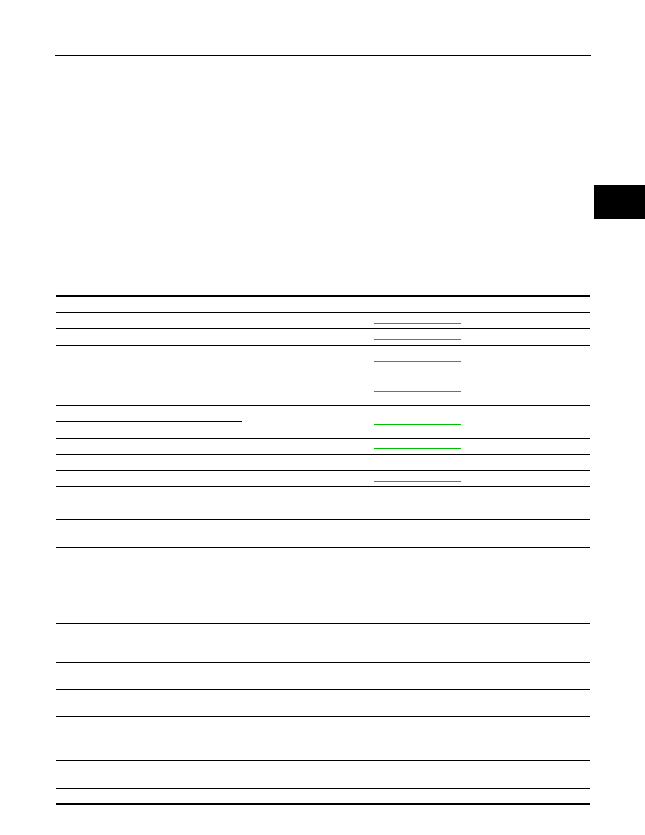
- TCM
- Turbine revolution sensor 1, 2
- Revolution sensor
- A/T fluid temperature sensor 1, 2
- PNP switch
- Line pressure solenoid valve
- Torque converter clutch solenoid valve
- Direct clutch solenoid valve
- High and low reverse clutch solenoid valve
- Input clutch solenoid valve
- Front brake solenoid valve
- Low coast brake solenoid valve
- ATF pressure switch 2
Component Description
INFOID:0000000001672108
A/T ASSEMBLY
Name
Function
TCM
PNP switch
Vehicle speed sensor A/T (Revolution sen-
sor)
Turbine revolution sensor 1
Turbine revolution sensor 2
A/T fluid temperature sensor 1
A/T fluid temperature sensor 2
Input clutch solenoid valve
Front brake solenoid valve
Direct clutch solenoid valve
High and low reverse clutch solenoid valve
Low coast brake solenoid valve
ATF pressure switch 2 (LC/B)
Detects any malfunction in the low coast brake hydraulic pressure. When it detects any
malfunction, it puts the system into fail-safe mode.
Torque converter regulator valve
In order to prevent the pressure supplied to the torque converter from being excessive,
the line pressure is adjusted to the optimum pressure (torque converter operating pres-
sure).
Pressure regulator valve
Pressure regulator plug
Pressure regulator sleeve
Adjusts the oil discharged from the oil pump to the optimum pressure (line pressure) for
the driving state.
Front brake control valve
When the front brake is coupled, adjusts the line pressure to the optimum pressure
(front brake pressure) and supplies it to the front brake. (In 1st, 2nd, 3rd, and 5th gears,
adjusts the clutch pressure.)
Accumulator control valve
Adjusts the pressure (accumulator control pressure) acting on the accumulator piston
and low coast reducing valve to the pressure appropriate to the driving state.
Pilot valve A
Adjusts the line pressure and produces the constant pressure (pilot pressure) required
for line pressure control, shift change control, and lock-up control.
Pilot valve B
Adjusts the line pressure and produces the constant pressure (pilot pressure) required
for shift change control.
Low coast brake switching valve
During engine braking, supplies the line pressure to the low coast brake reducing valve.
Low coast brake reducing valve
When the low coast brake is coupled, adjusts the line pressure to the optimum pressure
(low coast brake pressure) and supplies it to the low coast brake.
N-R accumulator
Produces the stabilizing pressure for when N-R is selected.