Infiniti G37 Coupe. Manual - part 1262


  Index      Infiniti     Infiniti G37 Coupe - service repair manual 2008 year


Search            


Content   ..  1260  1261  1262  1263   ..


Infiniti G37 Coupe. Manual - part 1262


C1911, C1912 4WAS REAR MOTOR POWER SUPPLY

STC-99

< COMPONENT DIAGNOSIS >

[WITH 4WAS]

C

D

E

F

H

I

J

K

L

M

A

B

STC

N

O

P

Is the inspection result normal?

YES

>> GO TO 8.

NO

>> Replace the noise suppressor.

8.

CHECK 4WAS REAR MOTOR POWER SUPPLY

1.

Install 4WAS rear motor relay.

2.

Install the noise suppressor.

3.

Turn the ignition switch ON.

CAUTION:

Never start the engine.

4.

Check the voltage between 4WAS main control unit harness connectors and the ground.

Is the inspection result normal?

YES

>> GO TO 9.

NO

>> Replace 4WAS main control unit. Refer to 

STC-178, "Exploded View"

.

9.

PERFORM SELF-DIAGNOSIS (4WAS MAIN CONTROL UNIT)

With CONSULT-III

Perform 4WAS main control unit self-diagnosis.

Is DTC “C1911” or “C1912” detected?

YES

>> Replace 4WAS main control unit. Refer to 

STC-178, "Exploded View"

.

NO

>> GO TO 10.

10.

CHECK INFORMATION

With CONSULT-III

Check the “DATA MONITOR” value of each DTC detected with the self-diagnosis function. Refer to 

STC-155,

"Reference Value"

.

Is each data the standard value?

YES

>> Check each harness connector pin terminal for disconnection.

NO

>> Replace 4WAS main control unit. Refer to 

STC-178, "Exploded View"

.

Component Inspection (4WAS Rear Motor Relay)

INFOID:0000000001666408

1.

CHECK 4WAS REAR MOTOR RELAY

1.

Turn the ignition switch OFF.

2.

Remove 4WAS rear motor relay connector.

3.

Apply 12 V to 4WAS rear motor relay connector No. 1 terminal and No. 2 terminal.

CAUTION:

• Never make the terminals short.
• Connect the fuse between the terminals when applying the voltage.

4.

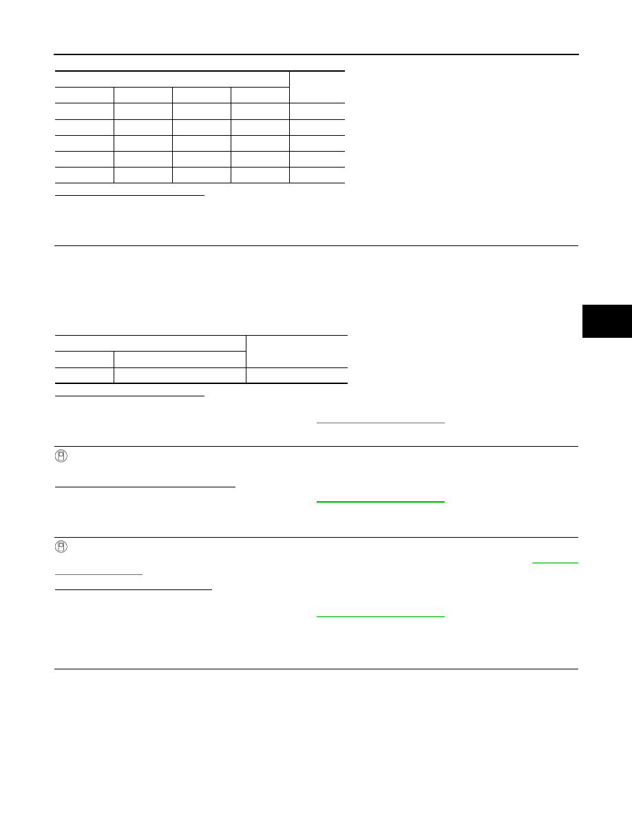
Check the continuity between 4WAS rear motor relay connector terminals.

Noise suppressor

Continuity

Connector

Terminal

Connector

Terminal

B51

3

B52

1

Existed

B51

3

B51

5

Not existed

B51

3

B52

2

Not existed

B51

5

B52

2

Existed

B51

5

B52

1

Not existed

4WAS main control unit

Voltage (Approx.)

Connector

Terminal

B54

37 – Ground

Battery voltage

STC-100

< COMPONENT DIAGNOSIS >

[WITH 4WAS]

C1911, C1912 4WAS REAR MOTOR POWER SUPPLY

5.

Check the resistance between 4WAS rear motor relay connector terminals.

Is the inspection result normal?

YES

>> INSPECTION END

NO

>> Replace 4WAS rear motor relay.

Component Inspection (Noise Suppressor)

INFOID:0000000001666409

1.

NOISE SUPPRESSOR INSPECTION

1.

Turn the ignition switch OFF.

2.

Remove the noise suppressor.

3.

Check continuity between the noise suppressor connector terminals.

Is the inspection result normal?

YES

>> INSPECTION END

NO

>> Replace the noise suppressor.

Special Repair Requirement

INFOID:0000000001666410

BEFORE REPLACING 4WAS MAIN CONTROL UNIT

• Record the self-diagnosis results (history).

CAUTION:

• Never erase the memory (history) of self-diagnosis results when replacing 4WAS main control unit

after diagnosis.

• Erase the memory of the self-diagnosis results (record) after printing out or recording all the val-

ues of “DATA MONITOR”.

4WAS rear motor relay

Continuity

Connector

Terminal

Condition

B53

3 – 5

Apply the voltage between 
No. 1 terminal and No. 2 ter-
minal.

Existed

Do not apply the voltage be-
tween No. 1 terminal and 
No. 2 terminal.

Not existed

4WAS rear motor relay

Resistance (Approx.)

Connector

Terminal

B53

1 – 2

50 

Noise suppressor

Continuity

Connector

Terminal

Connector

Terminal

B51

3

B52

1

Existed

B51

3

B51

5

Not existed

B51

3

B52

2

Not existed

B51

5

B52

2

Existed

B51

5

B52

1

Not existed

C1914 REAR WHEEL STEERING ANGLE SENSOR

STC-101

< COMPONENT DIAGNOSIS >

[WITH 4WAS]

C

D

E

F

H

I

J

K

L

M

A

B

STC

N

O

P

C1914 REAR WHEEL STEERING ANGLE SENSOR

Description

INFOID:0000000001666411

• It detects the steering angle condition of rear wheel.
• 2 systems (main and sub sensor) are equipped.

DTC Logic

INFOID:0000000001666412

DTC DETECTION LOGIC

DTC CONFIRMATION PROCEDURE

1.

RECHECK DTC

With CONSULT-III

1.

Turn the ignition switch from OFF to ON.

2.

Perform 4WAS main control unit self-diagnosis.

Is DTC “C1914” detected?

YES

>> Proceed to diagnosis procedure. Refer to 

STC-101, "Diagnosis Procedure"

.

NO

>> INSPECTION END

Diagnosis Procedure

INFOID:0000000001666413

1.

CHECK REAR WHEEL STEERING ANGLE SENSOR POWER SUPPLY

1.

Turn the ignition switch OFF.

2.

Check the voltage between 4WAS main control unit harness connector terminal and the ground.

3.

Turn the ignition switch ON.

CAUTION:

Never start the engine.

4.

Check the voltage between 4WAS main control unit harness connector terminal and the ground.

Is the inspection result normal?

YES

>> GO TO 2.

NO

>> Replace 4WAS main control unit. Refer to 

STC-178, "Exploded View"

.

2.

CHECK REAR WHEEL STEERING ANGLE SENSOR

1.

Turn the ignition switch OFF.

2.

Disconnect the rear wheel steering angle sensor harness connector.

3.

Check the resistance between the rear wheel steering angle sensor connector terminals.

DTC

Items

(CONSULT-III screen terms)

Diagnostic item is detected when...

Possible cause

C1914

RR ST ANGLE SENSOR
[ABNORML VOL]

The rear wheel angle sensor power supply error is de-
tected.

Rear wheel steering sen-
sor power supply error

4WAS main control unit

Voltage (Approx.)

Connector

Terminal

B54

5 – Ground

0 V

4WAS main control unit

Value (Approx.)

Connector

Terminal

B54

5 – Ground

5 V

STC-102

< COMPONENT DIAGNOSIS >

[WITH 4WAS]

C1914 REAR WHEEL STEERING ANGLE SENSOR

Is the inspection result normal?

YES

>> GO TO 3.

NO

>> Replace 4WAS rear actuator. Refer to 

STC-180, "Exploded View"

.

3.

CHECK REAR WHEEL STEERING ANGLE SENSOR POWER SUPPLY CIRCUIT

1.

Disconnect 4WAS main control unit harness connector.

2.

Check the continuity between 4WAS main control unit harness connector terminal and the rear wheel
steering angle sensor harness connector terminal.

Is the inspection result normal?

YES

>> GO TO 4.

NO

>> Repair or replace the harnesses and connectors.

4.

PERFORM SELF-DIAGNOSIS (4WAS MAIN CONTROL UNIT)

With CONSULT-III

1.

Connect 4WAS main control unit harness connector.

2.

Connect the rear wheel steering angle sensor harness connector.

3.

Perform 4WAS main control unit self-diagnosis.

Is DTC “C1914” detected?

YES

>> Replace 4WAS main control unit. Refer to 

STC-178, "Exploded View"

.

NO

>> GO TO 5.

5.

CHECK INFORMATION

With CONSULT-III

Check the “DATA MONITOR” value of each DTC detected with the self-diagnosis function. Refer to 

STC-155,

"Reference Value"

.

Is each data the standard value?

YES

>> Check each harness connector pin terminal for disconnection.

NO

>> Replace 4WAS main control unit. Refer to 

STC-178, "Exploded View"

.

Component Inspection

INFOID:0000000001666414

1.

CHECK REAR WHEEL STEERING ANGLE SENSOR

1.

Turn the ignition switch OFF.

2.

Disconnect rear wheel steering angle sensor harness connector.

3.

Check the resistance between rear wheel steering angle sensor connector terminals.

Rear wheel steering angle sensor

Resistance (Approx.)

Connector

Terminal

B35

1 – 3

1 k

1 – 2

1.2 – 1.5 k

1 – 4

1.2 – 1.5 k

4WAS main control unit

Rear wheel steering angle 

sensor

Continuity

Connector

Terminal

Connector

Terminal

B54

5

B35

1

Existed

B54

5

B35

3

Not existed

B54

15

B35

3

Existed

B54

15

B35

1

Not existed


Content   ..  1260  1261  1262  1263   ..