Infiniti G37 Coupe. Manual - part 1230


  Index      Infiniti     Infiniti G37 Coupe - service repair manual 2008 year


Search            


Content   ..  1228  1229  1230  1231   ..


Infiniti G37 Coupe. Manual - part 1230


ST-20

< ON-VEHICLE REPAIR >

LOWER SHAFT

LOWER SHAFT

WITHOUT 4WAS

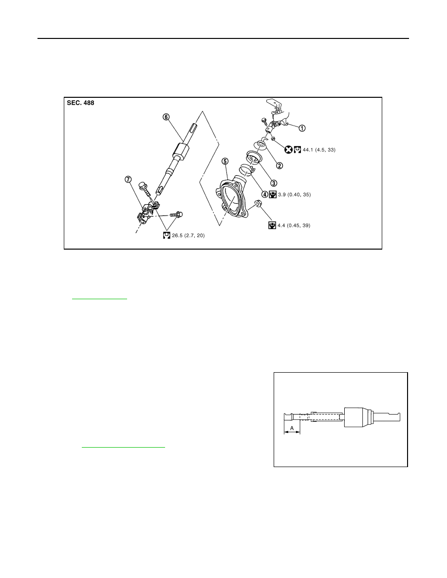
WITHOUT 4WAS : Exploded View

INFOID:0000000001666229

WITHOUT 4WAS : Removal and Installation

INFOID:0000000001666230

REMOVAL

1.

Set vehicle to the straight-ahead position.

2.

Fix the steering wheel.

3.

Remove lower joint fixing bolt (steering gear side).

4.

Separate the lower shaft from the steering gear assembly by
sliding the slide shaft (A: sliding range).

CAUTION:

Spiral cable may be cut if steering wheel turns while sepa-
rating steering column assembly and steering gear assem-
bly. Be sure to secure steering wheel using string to avoid
turning.

5.

Remove the accelerator pedal bracket and lever assembly.
Refer to 

ACC-3, "Exploded View"

.

6.

Remove the side brake wire clamp stay. (A/T models)

7.

Remove the hole cover mounting nuts.

8.

Remove the upper joint fixing bolt and nut (lower shaft side).

9.

Remove the lower shaft and hole cover.

10. Remove collar, hole cover seal, clamp and hole cover.

INSTALLATION

Note the following, and install in the reverse order of removal.

CAUTION:

Spiral cable may be cut if steering wheel turns while separating steering column assembly and steer-
ing gear assembly. Be sure to secure steering wheel using string to avoid turning.

1.

Steering column assembly

2.

Collar

3.

Hole cover seal

4.

Clamp

5.

Hole cover

6.

Lower shaft

7.

Lower joint

Refer to 

GI-4, "Components"

 for symbols in the figure.

JSGIA0157GB

JSGIA0035ZZ

LOWER SHAFT

ST-21

< ON-VEHICLE REPAIR >

C

D

E

F

H

I

J

K

L

M

A

B

ST

N

O

P

• Tighten the clamp to the specified torque and check the clamp

length (A).

• When installing lower joint to steering gear assembly, follow the

procedure listed below.

- Set rack of steering gear in the neutral position.

NOTE:
To get the neutral position of rack, turn gear-sub assembly and
measure the distance of inner socket, and then measure the inter-
mediate position of the distance.

- Align rear cover cap projection (A) with the marking position of

gear housing assembly (B).

- Install slit part of lower joint (C) aligning with the rear cover cap

projection (A). Make sure that the slit part of lower joint (C) is
aligned with rear cover cap projection (A) and the marking position
of gear housing assembly (B).

• Adjust neutral position of steering angle sensor. Refer to 

BRC-8,

"ADJUSTMENT OF STEERING ANGLE SENSOR NEUTRAL
POSITION : Special Repair Requirement"

. (VDC models)

• Check the following after installation:
- Check if steering wheel turns smoothly when it is turned several

times fully to the end of the left and right.

- Check the steering wheel play, neutral position steering wheel, steering wheel turning force, and front wheel

turning angle. Refer to 

ST-12, "Inspection"

.

WITHOUT 4WAS : Inspection

INFOID:0000000001666231

• Check the sliding range of the lower shaft.

CAUTION:

Check the sliding range (A) (between the extended position
and the contracted position) of the lower shaft.

• Check each part of lower shaft for damage or other malfunctions.

Replace if there are.

WITH 4WAS

WITH 4WAS : Exploded View

INFOID:0000000001666232

REMOVAL AND INSTALLATION

Clamp length “A”

: 14.0 – 18.0 mm (0.551 – 
0.709 in)

JSGIA0094ZZ

JSGIA0111ZZ

Standard

Sliding range

: Refer to 

ST-48, "Lower 

Shaft Sliding Range"

.

JSGIA0035ZZ

ST-22

< ON-VEHICLE REPAIR >

LOWER SHAFT

DISASSEMBLY AND ASSEMBLY

WITH 4WAS : Removal and Installation

INFOID:0000000001666233

REMOVAL

1.

Set vehicle to the straight-ahead position.

2.

Perform 4WAS front actuator neutral position adjustment. Refer to 

STC-27, "4WAS FRONT ACTUATOR

NEUTRAL POSITION ADJUSTMENT : Description"

. (4WAS models)

3.

Fix the steering wheel.

1.

Steering column assembly

2.

Hole cover assembly

3.

Lower shaft (With 4WAS front actua-
tor)

4.

Lower joint

Refer to 

GI-4, "Components"

 for symbols in the figure.

JSGIA0036GB

1.

Collar

2.

Hole cover seal

3.

Clamp

4.

Hole cover

5.

4WAS front actuator

6.

Hole cover (lower)

7.

Hole cover seal (lower)

8.

Clamp (lower)

9.

Slide shaft

Refer to

GI-4, "Components"

 for symbols in the figure.

JSGIA0087GB

LOWER SHAFT

ST-23

< ON-VEHICLE REPAIR >

C

D

E

F

H

I

J

K

L

M

A

B

ST

N

O

P

4.

Fix the lower shaft (with 4WAS front actuator) so that the posi-
tions (A) and (B) are aligned.

CAUTION:

Never damage the lower shaft (with 4WAS front actuator)
and hole cover.

5.

Remove lower joint fixing bolt (steering gear side).

6.

Separate the lower shaft (with 4WAS front actuator) from the
steering gear assembly by sliding the slide shaft (A: sliding
range).

CAUTION:

Spiral cable may be cut if steering wheel turns while sepa-
rating steering column assembly and steering gear assem-
bly. Be sure to secure steering wheel using string to avoid
turning.

7.

Remove the 4WAS front control unit. Refer to 

STC-177,

"Exploded View"

.

8.

Remove the accelerator pedal bracket and lever assembly.

9.

Remove the foot grille (right). Refer to 

VTL-48, "FOOT GRILLE :

Exploded View"

.

10. Remove the hole cover mounting nuts.

11. Remove the upper joint fixing bolt and nuts (lower shaft side).

12. Remove the lower shaft (with 4WAS front actuator) and hole cover assembly.

CAUTION:

Never damage the lower shaft (with 4WAS front actuator) and hole cover.

INSTALLATION

Note the following, and install in the reverse order of removal.

CAUTION:

Spiral cable may be cut if steering wheel turns while separating steering column assembly and steer-
ing gear assembly. Be sure to secure steering wheel using string to avoid turning.
• When installing lower joint to steering gear assembly, follow the procedure listed below.
- Set rack of steering gear in the neutral position.

NOTE:
To get the neutral position of rack, turn gear-sub assembly and measure the distance of inner socket, and
then measure the intermediate position of the distance.

- Align rear cover cap projection (A) with the marking position of

gear housing assembly (B).

- Install slit part of lower joint (C) aligning with the rear cover cap

projection (A). Make sure that the slit part of lower joint (C) is
aligned with rear cover cap projection (A) and the marking position
of gear housing assembly (B).

• Adjust neutral position of steering angle sensor. Refer to 

BRC-8,

"ADJUSTMENT OF STEERING ANGLE SENSOR NEUTRAL
POSITION : Special Repair Requirement"

.

• Check the following after installation:
- Check if steering wheel turns smoothly when it is turned several

times fully to the end of the left and right.

- Check the steering wheel play, neutral position steering wheel, steering wheel turning force, and front wheel

turning angle. Refer to 

ST-12, "Inspection"

.

- Perform 4WAS front actuator neutral position adjustment. Refer to 

STC-27, "4WAS FRONT ACTUATOR

NEUTRAL POSITION ADJUSTMENT : Description"

.

JSGIA0037ZZ

JSGIA0088ZZ

JSGIA0111ZZ


Content   ..  1228  1229  1230  1231   ..