Infiniti G37 Coupe. Manual - part 1155


  Index      Infiniti     Infiniti G37 Coupe - service repair manual 2008 year


Search            


Content   ..  1153  1154  1155  1156   ..


Infiniti G37 Coupe. Manual - part 1155


B2110 PNP/CLUTCH INTERLOCK SWITCH

SEC-117

< COMPONENT DIAGNOSIS >

[INTELLIGENT KEY SYSTEM]

C

D

E

F

G

H

I

J

L

M

A

B

SEC

N

O

P

1.

Turn ignition switch OFF.

2.

Disconnect IPDM E/R connector E5.

3.

Turn ignition switch ON.

4.

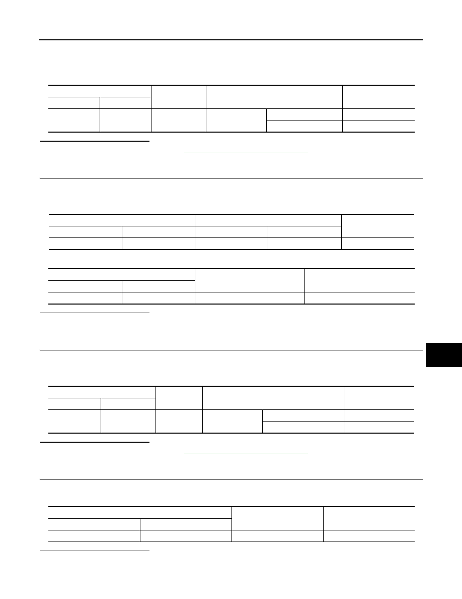
Check voltage between IPDM E/R harness connector and ground under following condition.

Is the inspection result normal?

YES

>> Replace IPDM E/R. Refer to 

PCS-34, "Removal and Installation"

.

NO

>> GO TO 4.

4.

CHECK PNP SWITCH CIRCUIT

1.

Turn ignition switch OFF.

2.

Disconnect A/T assembly connector.

3.

Check continuity between IPDM E/R harness connector and A/T assembly harness connector.

4.

Check continuity between IPDM E/R harness connector and ground.

Is the inspection result normal?

YES

>> GO TO 9.

NO

>> Repair harness or connector.

5.

CHECK CLUTCH INTERLOCK SWITCH INPUT SIGNAL

1.

Turn ignition switch OFF.

2.

Disconnect IPDM E/R connector E5.

3.

Check voltage between IPDM E/R harness connector and ground.

Is the inspection result normal?

YES

>> Replace IPDM E/R. Refer to 

PCS-34, "Removal and Installation"

.

NO

>> GO TO 6.

6.

CHECK CLUTCH INTERLOCK SWITCH POWER SUPPLY

1.

Disconnect clutch interlock switch connector.

2.

Check voltage between clutch interlock switch harness connector and ground.

Is the inspection result normal?

YES

>> GO TO 7.

NO

>> Check harness for open or short between clutch interlock switch and fuse.

IPDM E/R

Ground

Condition

Voltage (V)

Connector

Terminal

E5

30

Ground

A/T selector lever

P or N

Battery voltage

Other than above

0

IPDM E/R

A/T assembly

Continuity

Connector

Terminal

Connector

Terminal

E5

30

F51

9

Existed

IPDM E/R

Ground

Continuity

Connector

Terminal

E5

30

Ground

Not existed

IPDM E/R

Ground

Condition

Voltage (V)

Connector

Terminal

E5

30

Ground

Clutch pedal

 Not depressed

0

Depressed

Battery voltage

Clutch interlock switch

Ground

Voltage (V)

Connector

Terminal

E111

1

Ground

Battery voltage

SEC-118

< COMPONENT DIAGNOSIS >

[INTELLIGENT KEY SYSTEM]

B2110 PNP/CLUTCH INTERLOCK SWITCH

7.

CHECK CLUTCH INTERLOCK SWITCH CIRCUIT

1.

Check continuity between IPDM E/R harness connector and clutch interlock switch harness connector.

2.

Check continuity between IPDM E/R harness connector and ground.

Is the inspection result normal?

YES

>> GO TO 8.

NO

>> Repair harness or connector.

8.

CHECK CLUTCH INTERLOCK SWITCH

Refer to 

SEC-118, "Component Inspection"

.

Is the inspection result normal?

YES

>> GO TO 9.

NO

>> Replace clutch interlock switch.

9.

CHECK INTERMITTENT INCIDENT

Refer to 

GI-38, "Intermittent Incident"

.

>> INSPECTION END

Component Inspection

INFOID:0000000001700045

1.

CHECK CLUTCH INTERLOCK SWITCH

1.

Turn ignition switch OFF.

2.

Disconnect clutch interlock switch connector.

3.

Check continuity between clutch interlock switch terminals under the following conditions.

Is the inspection result normal?

YES

>> INSPECTION END

NO

>> Replace clutch interlock switch.

IPDM E/R

Clutch interlock switch

Continuity

Connector

Terminal

Connector

Terminal

E5

30

E111

2

Existed

IPDM E/R

Ground

Continuity

Connector

Terminal

E5

30

Ground

Not existed

Clutch interlock switch

Condition

Continuity

Connector

Terminal

E111

1

2

Clutch pedal

Not depressed

Not existed

Depressed

Existed

POWER SUPPLY AND GROUND CIRCUIT

SEC-119

< COMPONENT DIAGNOSIS >

[INTELLIGENT KEY SYSTEM]

C

D

E

F

G

H

I

J

L

M

A

B

SEC

N

O

P

POWER SUPPLY AND GROUND CIRCUIT

BCM

BCM : Diagnosis Procedure

INFOID:0000000001700046

1.

CHECK FUSE AND FUSIBLE LINK

Check that the following fuse and fusible link are not blown.

Is the fuse fusing?

YES

>> Replace the blown fuse or fusible link after repairing the affected circuit if a fuse or fusible link is

blown.

NO

>> GO TO 2.

2.

CHECK POWER SUPPLY CIRCUIT

1.

Turn ignition switch OFF.

2.

Disconnect BCM connectors.

3.

Check voltage between BCM harness connector and ground.

Is the measurement value normal?

YES

>> GO TO 3.

NO

>> Repair harness or connector.

3.

CHECK GROUND CIRCUIT

Check continuity between BCM harness connector and ground.

Does continuity exist?

YES

>> INSPECTION END

NO

>> Repair harness or connector.

BCM : Special Repair Requirement

INFOID:0000000001700047

1.

REQUIRED WORK WHEN REPLACING BCM

Initialize control unit. Refer to CONSULT-III operation manual NATS-IVIS/NVIS.

>> Work end.

IPDM E/R (INTELLIGENT POWER DISTRIBUTION MODULE ENGINE ROOM)

IPDM E/R (INTELLIGENT POWER DISTRIBUTION MODULE ENGINE ROOM) : Di-

Signal name

Fuse and fusible link No.

Battery power supply

K

10

Terminals

Voltage

(Approx.)

(+)

(

)

BCM

Ground

Connector

Terminal

M118

1

Battery voltage

M119

11

BCM

Ground

Continuity

Connector

Terminal

M119

13

Existed

SEC-120

< COMPONENT DIAGNOSIS >

[INTELLIGENT KEY SYSTEM]

POWER SUPPLY AND GROUND CIRCUIT

agnosis Procedure

INFOID:0000000001700048

1.

CHECK FUSES AND FUSIBLE LINK

Check that the following IPDM E/R fuses or fusible links are not blown.

Is the fuse fusing?

YES

>> Replace the blown fuse or fusible link after repairing the affected circuit if a fuse or fusible link is

blown.

NO

>> GO TO 2.

2.

CHECK POWER SUPPLY CIRCUIT

1.

Turn ignition switch OFF.

2.

Disconnect IPDM E/R connector.

3.

Check voltage between IPDM E/R harness connector and ground.

Is the measurement value normal?

YES

>> GO TO 3.

NO

>> Repair harness or connector.

3.

CHECK GROUND CIRCUIT

Check continuity between IPDM E/R harness connectors and ground.

Does continuity exist?

YES

>> INSPECTION END

NO

>> Repair harness or connector.

Terminal No.

Signal name

Fuses and fusible link No.

1

Battery power supply

C

50

51

Terminals

Voltage

(Approx.)

(+)

(

)

IPDM E/R

Connector

Terminal

Ground

E4

1

Battery voltage

2

IPDM E/R

Ground

Continuity

Connector

Terminal

E5

12

Existed

E6

41


Content   ..  1153  1154  1155  1156   ..