Infiniti G37 Coupe. Manual - part 1014


  Index      Infiniti     Infiniti G37 Coupe - service repair manual 2008 year


Search            


Content   ..  1012  1013  1014  1015   ..


Infiniti G37 Coupe. Manual - part 1014


PG

PREPARATION

PG-95

< PREPARATION >

[POWER SUPPLY&GROUND CIRCUIT]

C

D

E

F

G

H

I

J

K

L

B

A

O

P

N

PREPARATION

PREPARATION

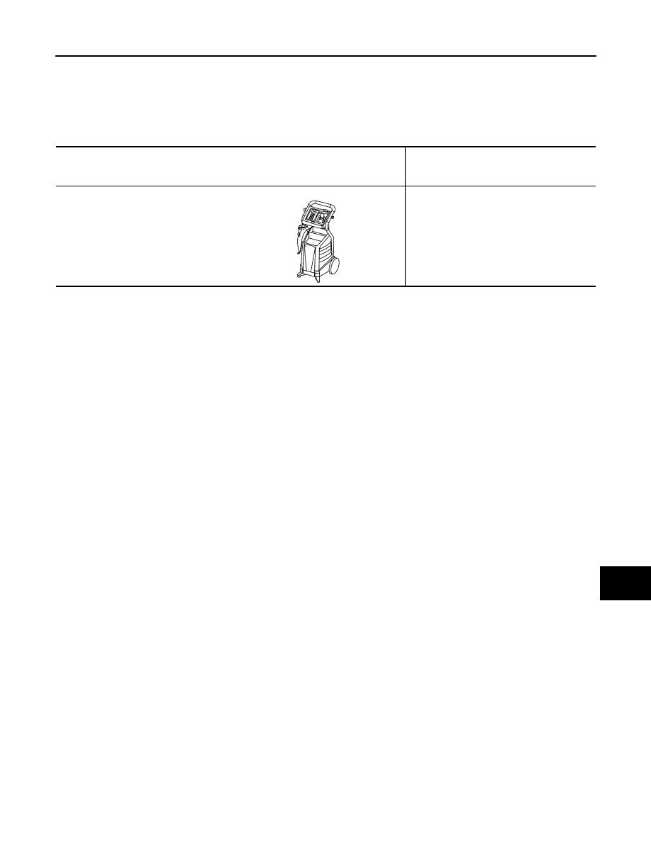
Special Service Tools

INFOID:0000000001680440

Tool number
(Kent-Moore No.)
Tool name

Description

(J-48087)
Battery Service Center

Tests battery.
For operating instructions, refer to Technical 
Service Bulletin and Battery Service Center 
User Guide.

WKIA5280E

PG-96

< ON-VEHICLE REPAIR >

[POWER SUPPLY&GROUND CIRCUIT]

BATTERY

ON-VEHICLE REPAIR

BATTERY

Exploded View

INFOID:0000000001680441

Removal and Installation

INFOID:0000000001680442

REMOVAL

1.

Remove battery cover.

2.

Remove the clips (A), and remove hoodledge cover RH (1).

3.

Remove the cowl top cover (RH). Refer to 

EXT-21, "Removal and Installation"

.

4.

Loosen battery terminal nuts (1), and disconnect both battery
cables from battery terminals. 

CAUTION:

When disconnecting, disconnect the battery cable from the
negative terminal first.

5.

Remove battery fix frame mounting nuts (2) and battery fix
frame (3).

6.

Remove battery.

INSTALLATION

Install in the reverse order of removal.

CAUTION:

When connecting, connect the battery cable to the positive terminal first.

1

: Battery fix frame

2

: Battery fix frame mounting nuts

3

: Battery terminal (-)

4

: Battery terminal (+)

JPMIA0487ZZ

JPMIA0488ZZ

JPMIA0489ZZ

Battery fix frame mounting nut

: 3.9 N·m (0.40 kg-m, 35 in-lb)

Battery terminal nut

: 5.4 N·m (0.55 kg-m, 48 in-lb)

PG

BATTERY TERMINAL WITH FUSIBLE LINK

PG-97

< ON-VEHICLE REPAIR >

[POWER SUPPLY&GROUND CIRCUIT]

C

D

E

F

G

H

I

J

K

L

B

A

O

P

N

BATTERY TERMINAL WITH FUSIBLE LINK

Exploded View

INFOID:0000000001680443

Removal and Installation

INFOID:0000000001680444

REMOVAL

1.

Disconnect the battery cable from the negative terminal.

2.

Remove cover of battery positive terminal.

3.

Remove harness mounting nuts (1) to disconnect harness con-
nector (2).

4.

Remove fusible link holder mounting nut (3) to disconnect bat-
tery terminal with fusible link (4).

INSTALLATION

Install in the reverse order of removal.

1

: Harness mounting nut

2

: Fusible link holder mounting nut

3

: Harness connector

4

: Battery terminal with fusible link

JPMIA0490ZZ

JPMIA0491ZZ

Harness mounting nut

: 13.2 N·m (1.3 kg-m, 10 ft-lb)

Fusible link holder mounting nut

: 13.2 N·m (1.3 kg-m, 10 ft-lb)

PG-98

< SERVICE DATA AND SPECIFICATIONS (SDS) 

[POWER SUPPLY&GROUND CIRCUIT]

SERVICE DATA AND SPECIFICATIONS (SDS)

SERVICE DATA AND SPECIFICATIONS (SDS)

SERVICE DATA AND SPECIFICATIONS (SDS)

Battery

INFOID:0000000001680445

Type

80D23L

20 hour rate capacity

[V - Ah]

12 - 62

Cold cranking current (For reference value)

[A]

582


Content   ..  1012  1013  1014  1015   ..